8.5.2 Building a Flow Graph
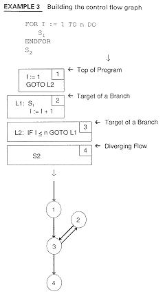
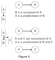
Formally, a flow graph is a directed graph G, with N nodes and E edges. (Remember that a directed graph is a connected set of nodes where every node is reachable from the initial node.) Example 3 shows the control flow graph for Example 2. The rules for building such a graph follow.

-
In Example 3, we see that the set of nodes is the set of basic blocks and the set of edges is determined by looking at places where the nodes branch.

