by Chris Bentley
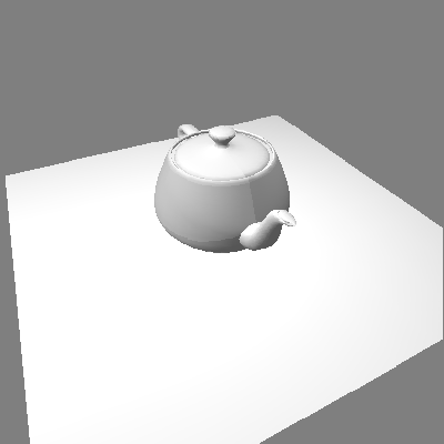
Object rendered with no shadow, appears to float above plane:

Case 1. light at infinity
Light source at infinity:
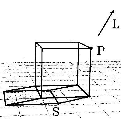
For the case of a light source positioned infinitely far away, we will assume that all the rays reaching the object are parallel. This will allow us to solve the shadow equations once, and apply the solutions to every vertex in our object. Given 2 points:


We want to calculate:
shadow point,

From similar triangles we have:

Solving for  :
:

If L is vector from point (P) to the light, then the Point-Vector form of the line is:

Since we require that  , this becomes:

or

Then, solving for  :
:

with  being similar.
In matrix form:

Now given the world coordinates of any polygon vertex, P , we can multiply:

This computes the projected shadow points of the polygon, which we can fill, producing a shadow polygon.
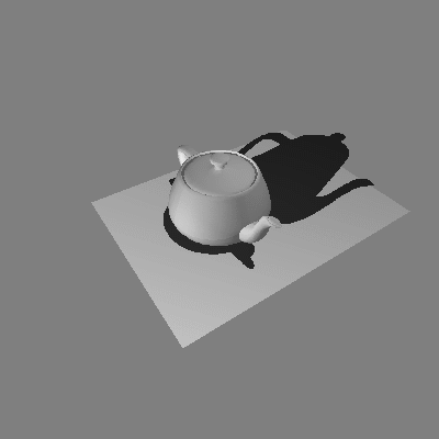
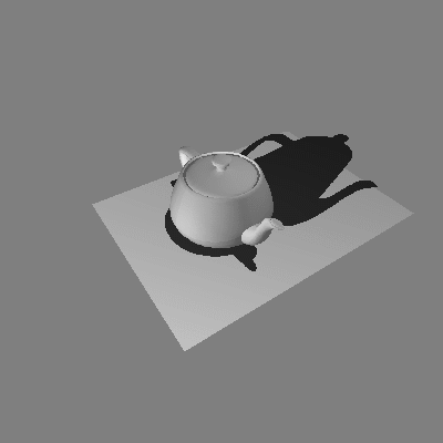
Shadows using "ground transformation" with two light sources at infinity:
Case 2. local light sources
Perspective shadow from local light source:
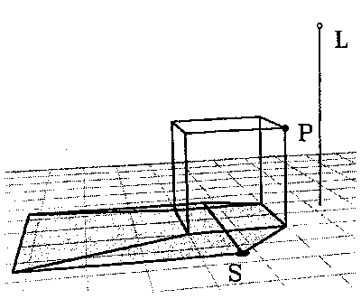
The equations for an infinite light source with parallel rays can be extended for the case of light sources that are positioned at some point in space, a finite distance away from the object being rendered. Note that now we will need to perform an additional calculation for every vertex in our object, because each vertex will, in general, have a different vector to the light. However, in this case too we can place most of our calculations in a matrix.
If, now, l is the location of the light source, and (P) is the polygon vertex, we can again use the Point-Vector form of the line:

Again, we require that  , so:
, so:

and

with  being similar.
By using the division performed when turning homogeneous coordinates into 3D coordinates, we can write the matrix:

Again, given the world coordinates of any polygon vertex, P , we can multiply:

and then homogenize to compute projected shadow point.
Shadows using "ground transformation" with local light source:
	/*
	 * get world coordinates of light
	 */
	copy_vect( light_point, view->lights[n]->world_coords );

	/*
	 * initialize shadow matrix, W, and then load rows, cols
	 */
	ident_mat( W );
	W[0][0] = -light_point[2];
	W[0][2] = light_point[0];
	W[1][1] = -light_point[2];
	W[1][2] = light_point[1];
	W[2][2] = 0;
	W[3][3] = -light_point[2];
And here is the code for multiplying a polygon's world coordinates by the shadow matrix to project the polygon onto the z = 0 plane:
	/*
	 * transform object world coordinates into z = 0 plane, using W matrix
	 */
	pt_matrix_mult( wpt, W, v[i].world_coords );
	homo( v[i].world_coords );

	/*
	 * transform new coordinates of shadow point by viewing
	 * and perspective transformations
	 */
	pt_matrix_mult( v[i].world_coords,cur_view->VPN,v[i].screen_coords);
	homo( v[i].screen_coords );
The Z-buffer method involves looking at the object from the point of view of each light in the scene, and computing a Z-buffer of the object as seen by each light. After this preprocessing is performed, the object is rendered from the "true" eye position. For every pixel visible to the eye, we will transform the object point into the light's view to determine whether that point was also visible to the light. If it was not, then that point is in shadow.
Note that when we are calculating the hidden surfaces from the point of view of each light source, we only care about the depth information, and we are not interested in performing lighting calculations for these polygons, because the "light's eye views" will not normally be seen by the user. This permits faster rendering when precalculating the shadow Z-buffers.
1.0  for each light source
1.1      make light point be center of projection
1.2      calculate transformation matrices
1.3      transform object using light point matrices
1.4      render object using zbuffer - lighting is skipped
1.5      save computed zbuffer (depth info)
Object rendering phase
2.0  make eye point be center of projection
3.0  recalculate transformation matrices
4.0  transform object using eye point matrices
5.0  render object using zbuffer

5.1      for every pixel visible from eye
5.1.1        transform world point corresponding to pixel to shadow coordinates
5.1.2        for every light source
5.1.2.1          sample saved zbuffer for that light
5.1.2.2          if shadow coordinates < zbuffer value
5.1.2.2.1            pixel is in shadow
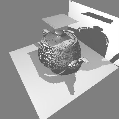
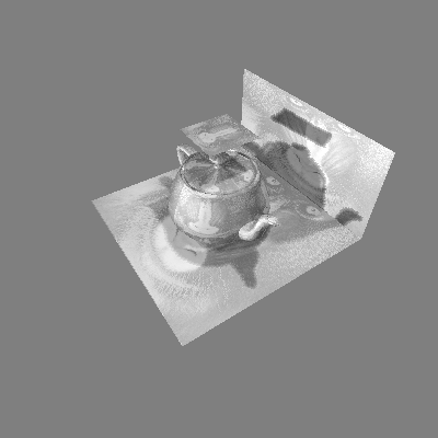
The solution to the problem of points "shadowing themselves" is to cheat a little: when transforming the point into shadow coordinates to see whether it is obscured by anything, we add a small fudge factor so that points project in front of themselves, and thus do not shadow themselves. The solution to the problem of comparing with the wrong Z-buffer values is to perform "Area Sampling" of the Z-buffer around the projected point, rather than just "Point Sampling". However, simply averaging the Z-buffer values in the neighborhood is not sufficient. A better solution is "Percent Closer Filtering", as described in Watt [Watt]. This method also provides a small amount of antialiasing of shadow edges, which produces shadows with slightly softer edges.
Object as viewed from light #1:
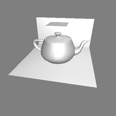
Object as viewed from light #2:
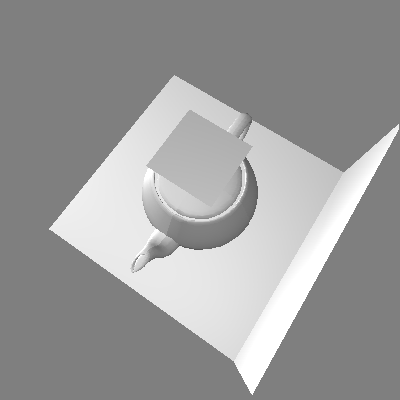
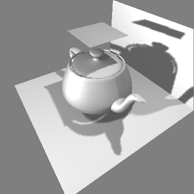
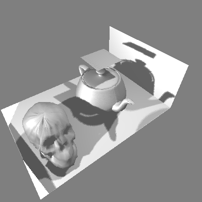
The Z-buffer algorithm produces shadows not only on z = 0 plane:
A. The Ground Transformation Algorithm
B. The Z-Buffer Algorithm
The Z-buffer algorithm is clearly more versatile, with its ability to add shadows to scenes of arbitrary complexity. Also the precomputed shadow buffers can be used to render views from any eye point as long as the relative positions of the lights and objects are constant between these views. However, if memory resources are limited, the ground transformation algorithm produces pleasing results if only ground shadowing is required.
Shadowing of texture mapped objects:
Visible surfaces shadowing themselves:
