2. Components
The following are components used in this experiment.
Open vSwitch
Physical Router: TP-Link Archer C7 AC1750
Next I will introduce them one by one.
2.1 OpenWrt
Generally speaking, OpenWrt is an open source linux-like OS runs on routers/switches. It has to be flashed into compatible routers. The steps and useful links will be introduced later. Users can use linux commands and configuration files to set up OpenWrt. It also come with a GUI.
2.1.1 Flash your router with OpenWrt
Generally speaking, you can flash a router with OpenWrt by the firmware provided by the official site. After downloading it, you can update your router by the GUI of your router. You can access by http://192.168.0.1 or http://192.168.1.1, depends on your router.
If your router is already flashed with OpenWrt and you want to update the firmware, you can use the same method by accessing http://192.168.1.1. This is the default gateway used by OpenWrt, unless you have changed it. Beside, you can also download the current OpenWrt as a backup of your configuration, or you need to duplicate the configuration to other routers.
There is a packets manager tool named opkg. (check usage by man opkg) Unfortunately, due to some reasons, I'm not sure if
you can use opkg install OVS successfully now. (Technically it should work). If you are going to play with
OpenWrt for a long term, I'd suggest try to build the kernel by your self from source. The process is just like
building a LKM (Linux Kernel Module). Don't forget to click on the Open vSwitch while the building. The tutorial
: Build OpenWrt from source.
After your OpenWrt router is all set, you can try to log in and start your journey. Remember the default gateway
is 192.168.1.1, if you didn't update it. Connect to your OpenWrt, wired or wireless. Then open
your terminal and execute telnet 192.168.1.1. You should be able to log in the router and see the
interface below. 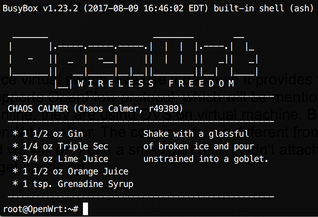 As you can see, you logged as root, but you don't
know the password for root. So, at this time, you cannot even log in through the GUI (http://192.168.1.1) and you
can only log in with telnet. Then, execute
As you can see, you logged as root, but you don't
know the password for root. So, at this time, you cannot even log in through the GUI (http://192.168.1.1) and you
can only log in with telnet. Then, execute passwd and enter your strong password twice. After confirmed,
you can exit and try if you still can log in with telnet. Hopefully not because you have activated ssh connection
and this is the only way you can log in from terminal. Try log in with ssh root@192.168.1.1. If
it works, you should also be able to access the web GUI.
2.1.2 Reset a router flashed with OpenWrt
I can't even remember how many times I have reset the router after it's down, due to some bad configuration. So it's important to clarify how to reset a OpenWrt.
Stage 1: Poweroff the router and unplug any cables (except power cable), especially make sure there is nothing on
WAN port.
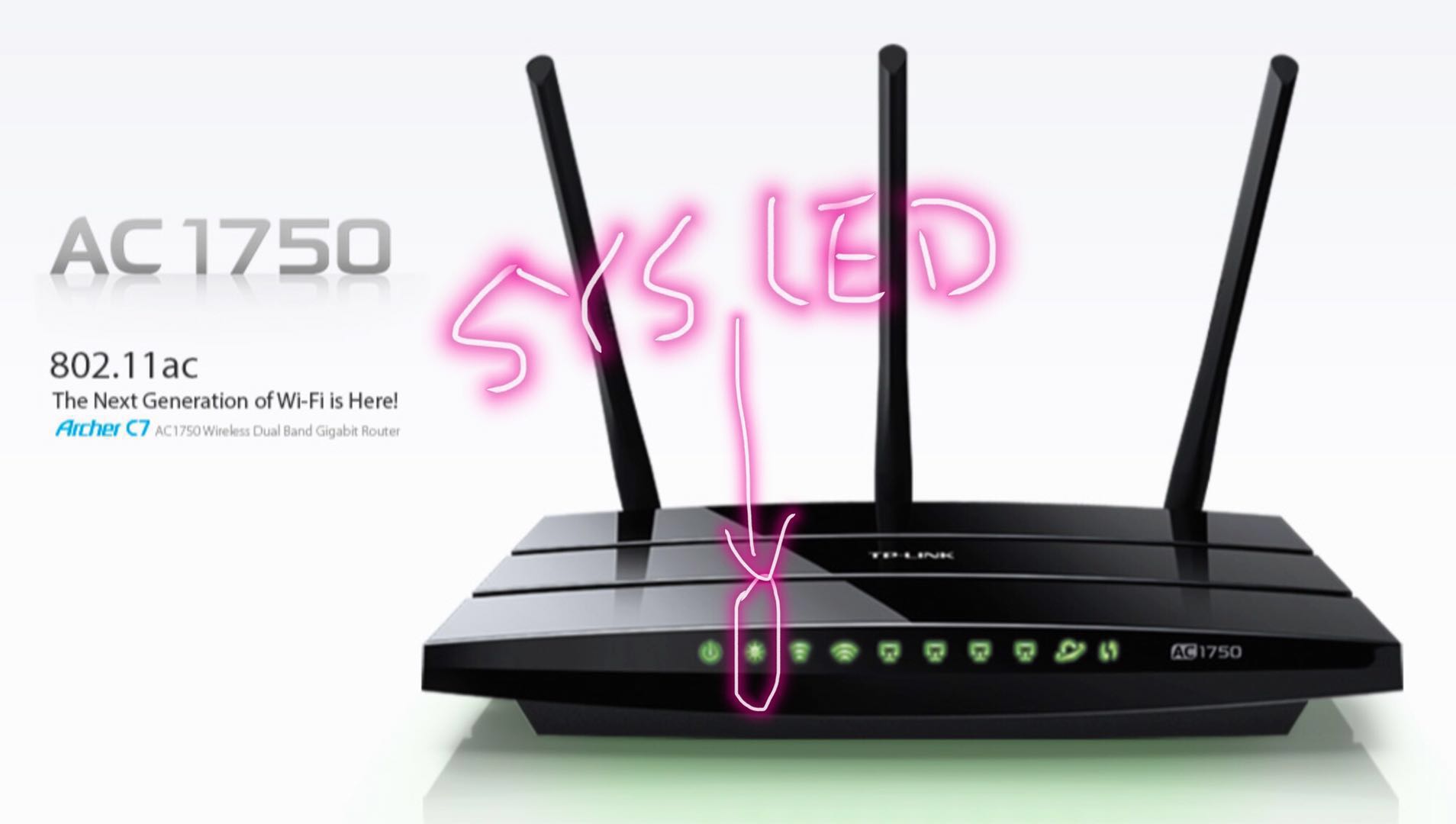
Stage 2: Turn on the router and hold the reset button of the router very soon. Wait for a while, it will restart.
Keep your eye on SYS LED on the router. If it starts blinking faster, it means you are in the failsafe mode. Otherwise,
do the steps again.
Stage 3: After you are in failsafe mode, plug an ethernet cable onto WAN port, the other side connected to you laptop.
I don't think at this time your laptop is assigned an IP address by dhcp server of the router, so you need to
manually setup your IP address as 192.168.1.* to make your laptop and the router in the same subnet.
Then you should be able to use telnet log in the router again.
Stage 4: Then you should delete the previous setups, thus router can be reset. All your files will be removed unless
some of them are embedded in the firmware. The commands you need to run are
            mount_root
            mtd -r erase rootfs_data
Then it will automatically restart. Stage 5: Unplug the cable from WAN port and plug it to any other ports, you can continue exploring.
2.3 Open vSwitch
To be brief, we will call it OVS. OVS is an open source virtual switch. We use it because it provides the connection to remote controller. In other words, it supports OpenFlow protocol, which will be mentioned later on. For many other experiments you can find online, they are using OVS on virtual machine. But we are going to use it on a physical router, with OpenWrt together, which is harder than on the VMs. Also, the related commands are different from using it on linux machine. It's not hard to use, but there is a great video shows how to set it up on VMs. It's important to understand how to set up the interfaces and bridge to make VMs connect to the host machine and also the internet. After this, transferring to physical router could be much easier. About how to install OVS on a physical router I have mentioned in the section of building OpenWrt kernel.
2.4 OpenFlow protocol
OpenFlow plays a vital role in SND, also in our experiment. It's the most common used protocol currently on SDN network. Controllers could be built with different languages, while majority of them use OpenFlow as an interface. So you see how important to know OpenFlow well. It's important to read part of the latest version OpenFlow specification. There's a lot of staff. You don't have to read all of it right now. Just read by part through the whole experiment process.
2.5 Floodlight
We use Floodlight on our controller. It's based on Java. Floodlight provides not only the basic functionalities that a controller should have, but also many other built-in modules.
The modules are independent to each other. According to the flow table on OVS router, some of the packets will be elevated to the controller, seen as PACKET_IN. Each of the PACKET_IN will be copied to each module. Modules will process the packets and make decisions how to deal with the PACKET_IN. But controller cannot do the actions itself. But they can use OpenFlow to tell OVS router how to do with each cases. Different module usually has different functionalities. In our experiment we are going to build our application on controller as one of the modules.
Installation of Floodlight is not hard. Just follow the steps you should be fine.
Some useful website about Floodlight.
Floodlight wiki
Floodlight Forum, which is very useful.
Java documentation. Convenient to lookup any packages
or built-in modules.
2.6 Router
The router I'm using is a really great one. The detailed information about this specific model (AC1750) can be accessed by clicking on the above link. If you already have a router, it's not promised it's compatible with OpenWrt. If you want to buy other routers, depends on need, for this kind of SDN experiment, you should first refer this link.
Some basic knowledge about physical router is important. If not clear with those concepts the experiment will be hard to understand.
Firstly, please check if you understand hub, switch and router.
Secondly, I want to show a figure (can be found here).
about the router we are about to use. 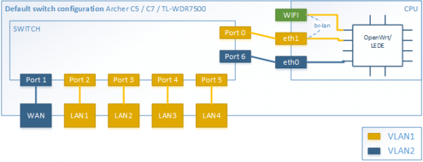
The figure is provided by OpenWrt. The vlan configuration is set by default when the router is flashed. Notice
the port numbers are different from the router we use. Using wrong ones could makes the flows invalid and it's
hard to debug, which misguided me for a long while. Here I'm using the figure to introduce the inner structure
of the router. As you can see, a router consists of two different parts, switch and CPU. Our primary goal is to use
VLAN divide the ports in different VLANs. Then the devices connected to different port are just like connected to
different subnets. Why we want to use VLAN? Because we want to monitor all the traffic by the controller. But the
problem is, if we put, for example, port2 and port3 in the same VLAN, they will be able to talk with each other
directly. The traffic is not going through the CPU. As CPU cannot see the packets, of course OVS cannot match the
packets or elevate them to floodlight. Because OpenWrt and Open vSwitch are both installed on the CPU section of the router.
For a counterexample, you can see there is a wifi port. All devices
connected to the router by wireless network are connected to this specific port. So all of them are in the same VLAN. Traffic between
them are not going through the CPU.
Thus the CPU will never see any packets between those devices.
You may ask, we are working on residential network, right?
Every devices at home are connected with WI-FI. How do we do the experiment if we cannot see the packets? Well,
you are right, it should be. The isolation of wireless network devices could be explored in the future. We propose
another solution.
Though, ports of different VLAN should be connected with each other, and also the CPU. We need the define a path
to let them talk. Okay, in VLAN, we can set up a tagged port. That one specific port can be assigned to different
VLANs simultaneously. If both VLAN1 and VLAN2 has the same tagged port, devices in VLAN1 and talk to any devices
in VLAN2. All of those can be set in the OpenWrt configuration file /etc/config/network. The guidance
for configuring this file can be found HERE. I will cover
some essential points in the coming sections.
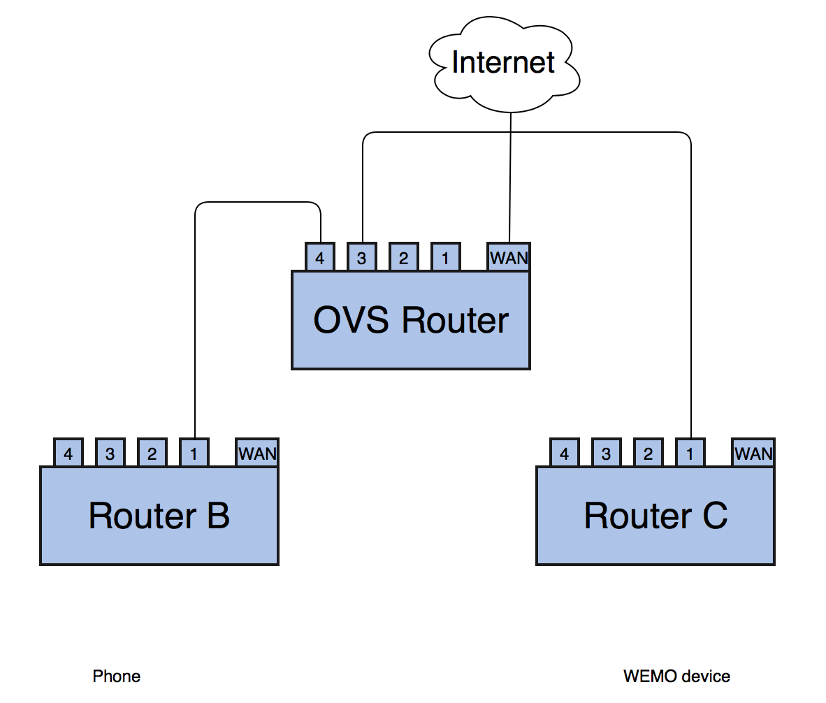
2.7 WEMO Smart Switch
The functionality of this device is quite simple, on and off. It can be controlled by an App on mobile phone. When the cell phone and WEMO are in the same subnet, they can directly talk with each other with plaintext traffic, though WEMO periodically sends keep alive messages to a remote server, provided by device manufacturer. When they are not located in the same subnet, they have to communicate via the server. And packets are encrypted.