Introduction

Environment mapping is a scheme that improves on the mapping techniques of chrome and refraction mapping.
It is useful because of the fact that in a reflective environment, ray tracing can be very expensive. Environment mapping gives these reflections more cheaply with little loss of accuracy.

Its computation is independent of the level of detail of the surroundings. In environment mapping, the object is surrounded by a closed three dimensional surface onto which the environment is projected. Reflected rays are traced from the object, hit the surface and then index onto the map. It is essentially the sam e as chrome mapping except that the map consists of an image of the environment as seen from the center of the space to be environment mapped.

Factors affecting environment mapping

In all environment mapping techniques, the accuracy depends on the object being positioned in the center of the surface and that objects in the environment are distant from the objects receiving the enviroment map. As the object becomes large with respect to the environment or the distance from the map center increases, the geometric distortion increases. This is because of the fact that, the environment map is created as a projection from a single point at the center of the surface.
Geometric distortion can be reduced by ray tracing those objects in the environment that are too close to the reflective object. If the reflective object is to complex, it may have to be ray traced which environment mapping cannot handle.

Techniques of environment mapping

  • The first use of environment mapping was developed by Jim Blinn and Newell. In this case, the object is deemed to be positioned at the center of a large sphere, onto the interior, of which the environment is projected. The mapping used a latitude-longitude map indexed by the reflected ray, similar to chrome mapping.
    The index function uses only the direction of R, leading to errors in planar surfaces on large objects that will tend to index onto the same point on the map. Also, mapping is essentially a spherical projection and contains a singularity at (0,0,Rz).
    In chrome mapping, this gave rise to spikes whereas in this case, distortions arise in the map around the singularities. This is a degradation as it contributes to the final effect. The difference between longitude-latitude mapping and chrome mapping is that in the former, the map is the environment whereas in the latter, the map is an arbitrary image.
    In terms of implementation, both of them are identical.
  • The other environment technique is one in which the environment is projected onto the six sides of the cube.
    The mapping function R3 -> R2 is no longer spherical and so much less distortion.Environment maps are constructed by taking six images, from a fixed point, in mutually orthogonal directions either with a camera whose field of view is PI/2 or by using a renderer to construct the maps from a modeled scene.These six images are then converted into six mip-maps. The problem with using a real camera is tat it is difficult to construct six component map without encountering both geometric and illumination discontinuities at the seams or boundaries. This technique is popular as it gives a neat way of blending computer generated objects and live action sets.

    Let us now look at a few examples of environment mapping

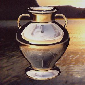
    This figure shows a vase against a background.


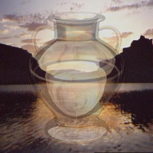
    This figure shows a vase which is highly transparent against a background.


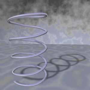
    This figure shows chrome mapping with soft shadows.


    Back to the main screen


    Copyright - Sudhir R Kaushik (sudhir@cs.wpi.edu)