Another distinction of NURBS concerns the parametrization of the surface. When uniform surfaces are always evaluated in their entirety, a non uniform surface can be obtained using a sub range of values.
Patches
Patches can be either uniform or non-uniform (contain different knot values). Patches can also be rational or non-rational depending on whether the control points are (x,y,z) or (x,y,z,w). Patches may also be bilinear or bicubic. The graphics state maintains two 4x4 matrices that define the bicubic patch basis matrices. One of these is the current u-basis and the other is the current v-basis. Basis matrices are used to transform from the power basis to the preferred basis.
RiBasis( ubasis, ustep, vbasis, vstep )
	RtBasis	ubasis, vbasis;
	RtInt	ustep, vstep;
Set the current u-basis to ubasis and the current v-basis to vbasis. Predefined basis matrices exist for the common types:
	RtBasis	RiBezierBasis;
	RtBasis	RiBSplineBasis;
	RtBasis	RiCatmullRomBasis;
	RtBasis	RiHermiteBasis;
	RtBasis	RiPowerBasis;
The variables ustep and vstep specify the number of control points that should be skipped in the u and v directions, respectively, to get to the next patch in a bicubic patch mesh. The appropriate step values for the predefined cubic basis matrices are:
| Basis | Step |
|---|---|
| RiBezierBasis | 3 |
| RiBSplineBasis | 1 |
| RiCatmullRomBasis | 1 |
| RiHermiteBasis | 2 |
| RiPowerBasis | 4 |
The default basis matrix is RiBezierBasis in both directions.
RIB BINDING

	Basis uname ustep vname vstep
	Basis uname ustep vbasis vstep
	Basis ubasis ustep vname vstep
	Basis ubasis ustep vbasis vstep
For each basis, either the name of a predefined basis (as a string) or a matrix may be supplied. If a basis name specified, it must be one of: "bezier", "b-spline", "catmull-rom", "hermite", or "power."
EXAMPLE

	Basis "b-spline" 1 [-1 3 -3 1 3 -6 3 0 -3 3 0 0 1 0 0 0] 1
Note that the geometry vector used with the RiHermiteBasis basis matrix must be (point0, vector0, point1, vector1), which is a permutation of the Hermite geometry vector often found in mathematics texts. Using this formulation permits a step value of 2 to correctly increment over data in Hermite patch meshes.
RiPatch( type, parameterlist )
	RtToken	type;
Define a single patch. type can be either "bilinear" or "bicubic". parameterlist is a list of token-array pairs where each token is one of the standard geometric primitive variables or a variable which has been defined with RiDeclare. The parameter list must include at least position ("P", "Pw" or "Pz") information. Patch arrays are specified such that u varies faster than v.
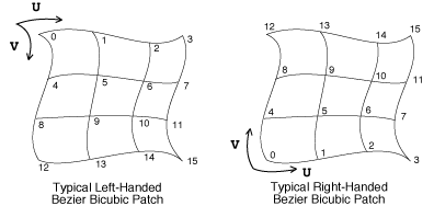
Four points define a bilinear patch, and 16 define a bicubic patch. The order of vertices for a bilinear patch is (0,0),(1,0),(0,1),(1,1). Note that the order of points defining a quadrilateral is different depending on whether it is a bilinear patch or a polygon. The vertices of a polygon would normally be in clockwise (0,0),(0,1),(1,1),(1,0) order.
Patch primitive variables which are uniform should supply one value, which is constant over the patch. Primitive variables which are varying should supply four values, one for each parametric corner of the patch. The actual size of each array is this number of values times the size of the type associated with the variable.
RIB BINDING

	Patch type parameterlist

EXAMPLE

	Patch "bilinear" "P" [ -0.08 0.04 0.05  0 0.04 0.05
		-0.08 0.03 0.05  0 0.03 0.05]
Bicubic patch vertex ordering

RiPatchMesh( type, nu, uwrap, nv, vwrap, parameterlist )
	RtToken	type;
	RtToken	uwrap, vwrap;
	RtInt	nu, nv;
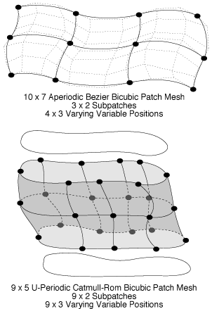
This primitive is a compact way of specifying a quadrilateral mesh of patches. Each individual patch behaves as if it had been specified with RiPatch. type can be either "bilinear" or "bicubic." parameterlist is a list of token-array pairs where each token is one of the geometric primitive variables or a variable which has been defined with RiDeclare. The parameter list must include at least position ("P", "Pw" or "Pz") information. Patch mesh vertex data is supplied in first u and then v order just as for patches. The number of control points in a patch mesh is (nu)*(nv).
Meshes can wrap around in the u or v direction, or in both directions. If meshes wrap, they close upon themselves at the ends and the first control points will be automatically repeated. As many as three control points may be repeated, depending on the basis matrix of the mesh. The way in which meshes wrap is indicated by giving a wrap mode value of either "periodic" or "nonperiodic."
The actual number of patches produced by this request depends on the type of the patch and the wrap modes specified. For bilinear patches, the number of patches in the u direction, nupatches, is given by

while for bicubic patches,

The same rules hold in the v direction. The total number of patches produced is equal to the product of the number of patches in each direction.
If a variable other than position varies, it contains n values, one for each patch corner, where n is defined by:

(with nupatches and nvpatches defined as given above). If a variable is uniform, it contains nupatches*nvpatches elements of its type, one for each patch.
A patch mesh is parameterized by a (u,v) which goes from 0 to 1 for the entire mesh. Texture maps that are assigned to meshes that wrap should also wrap so that filtering at the seams can be done correctly. If texture coordinates are inherited from the graphics state, they correspond to the corners of the mesh.
Height fields can be specified by giving just a z coordinate at each vertex (using "Pz"); the x and y coordinates are set equal to the parametric surface parameters. Height fields cannot be periodic.
RIB BINDING

	PatchMesh type nu uwrap nv vwrap parameterlist

EXAMPLE

	RtPoint pts[28]
	RtFloat foos[2];
	RtFloat bars[6];

	RiBasis(RiBezierBasis, 3, RiBezierBasis, 3);
	RiDeclare("foo", "uniform float");
	RiDeclare("bar", "varying float");
	RiPatchMesh("bicubic", 7, "nonperiodic", 4, "nonperiodic",
		"P", (RtPointer)pts, "foo", (RtPointer)foos,
		"bar", (RtPointer)bars, RI_NULL);
Patch meshes

Non-uniform B-spline patches are also supported by the RenderMan Interface. Rational quadratic B-splines provide exact representations of many different surfaces including general quadrics, tori, surfaces of revolution, tabulated cylinders, and ruled surfaces.
RiNuPatch( nu, uorder, uknot, umin, umax, nv, vorder, vknot, vmin, vmax,
		parameterlist )
	RtInt	nu, nv;
	RtInt	uorder, vorder;
	RtFloat	uknot[], vknot[];
	RtFloat	umin, umax, vmin, vmax;
This procedure creates a tensor product rational or polynomial non-uniform B-spline surface patch mesh. parameterlist is a list of token-array pairs where each token is one of the standard geometric primitive variables or a variable that has been defined with RiDeclare. The parameter list must include at least position ("P" or "Pw") information.
The surface specified is rational if the positions of the vertices are 4-vectors (x,y,z,w), and polynomial if the positions are 3-vectors (x,y,z). The number of control points in the u direction equals nu and the number in the v direction equals nv. The total number of vertices is thus equal to (nu)*(nv). The order must be positive and is equal to the degree of the polynomial basis plus 1. There may be different orders in each parametric direction. The number of control points should be at least as large as the order of the polynomial basis. If not, a spline of order equal to the number of control points is computed. The knot vectors associated with each control point (uknot[], vknot[]) must also be specified. Each value in these arrays must be greater than or equal to the previous value. The number of knots is equal to the number of control points plus the order of the spline. The surface is defined in the range umin to umax and vmin to vmax. This is different from other geometric primitives where the parameter values are always assumed to lie between 0 and 1. Each min must be less than its max. min must also be greater than or equal to the corresponding (order-1)th knot value. max must be less than or equal to the nth knot value.
If texture coordinates primitive variables are not present, the current texture coordinates are assigned to corners defined by the rectangle (umin,umax) and (vmin,vmax) in parameter space.
RIB BINDING NuPatch nu uorder uknot umin umax nv vorder vknot vmin vmax parameterlist EXAMPLE NuPatch 9 3 [ 0 0 0 1 1 2 2 3 3 4 4 4 ] 0 4 2 2 [ 0 0 1 1 ] 0 1 "Pw" [ 1 0 0 1 1 1 0 1 0 2 0 2 -1 1 0 1 -1 0 0 1 -1 -1 0 1 0 -2 0 2 1 -1 0 1 1 0 0 1 1 0 -3 1 1 1 -3 1 0 2 -6 2 -1 1 -3 1 -1 0 -3 1 -1 -1 -3 1 0 -2 -6 2 1 -1 -3 1 1 0 -3 1 ]RiTrimCurve( nloops, ncurves, order, knot, min, max, n, u, v, w ) RtInt nloops RtInt ncurves[]; RtInt order[]; RtFloat knot[]; RtFloat min[], max[]; RtInt n[]; RtFloat u[], v[], w[];
NURBS may contain holes that are specified by giving a single closed curve in parameter space.
Set the current trim curve. The trim curve contains nloops loops, and each of these loops contains ncurves curves. The total number of curves is equal to the sum of all the values in ncurves. Each of the trimming curves is a non-uniform rational B-spline curve in homogeneous parameter space (u,v,w). The curves of a loop connect in head-to-tail fashion and must be explicitly closed. The arrays order, knot, min, max, n, u, v, w contain the parameters describing each trim curve. All the trim curve parameters are concatenated together into single large arrays. The meanings of these parameters are the same as the corresponding meanings for a non-uniform B-spline surface.
Trim curves exclude certain areas from the non-uniform B-spline surface definition. The inside must be specified consistently using two rules: an odd winding rule that states that the inside consists of all regions for which an infinite ray from any point in the region will intersect the trim curve an odd number of times, and a curve orientation rule that states that the inside consists of the regions to the ``left'' as the curve is traced.
Trim curves are typically used to specify boundary representations of solid models. Since trim curves are approximations and not exact, some artifacts may occur at the boundaries between intersecting output primitives. A more accurate method is to specify solids using spatial set operators or constructive solid geometry (CSG).
If the particular implementation does not support Trim Curves, all trim curves are ignored and the entire NURB surface is always rendered.
RIB BINDING

	TrimCurve ncurves order knot min max n u v w
The number of loops is determined implicitly by the length of the ncurves array.
EXAMPLE

	RtInt nloops = 1;
	RtInt ncurves[1] = { 1 };
	RtInt order[1] = { 3 };
	RtFloat knot[12] = { 0,0,0,1,1,2,2,3,3,4,4,4 };
	RtFloat min[1] = { 0 };
	RtFloat max[1] = { 4 };
	RtInt n[1] = { 9 };
	RtFloat u[9] = {  1.0, 1.0, 1.0, 0.0, 0.0, 0.0, 1.0, 1.0, 1.0 };
	RtFloat v[9] = {  0.5, 1.0, 2.0, 1.0, 0.5, 0.0, 0.0, 0.0, 0.5 };
	RtFloat w[9] = {  1.0, 1.0, 2.0, 1.0, 1.0, 1.0, 2.0, 1.0, 1.0 };

	RiTrimCurve(nloops, ncurves, order, knot, min, max, n, u, v, w);
Copyright - Sudhir R Kaushik (sudhir@cs.wpi.edu)