8.5.2 Building a Flow Graph
A flow graph shows all possible execution paths. We will use this information to perform optimizations.
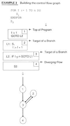
Formally, a flow graph is a directed graph G, with N nodes and E edges. (Remember that a directed graph is a connected set of nodes where every node is reachable from the initial node.) Example 3 shows the control flow graph for Example 2. The rules for building such a graph follow.

In Example 3, we see that the set of nodes is the set of basic blocks and the set of edges is determined by looking at places where the nodes branch.
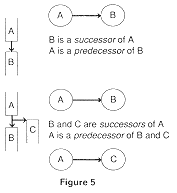
More formally, we create nodes and arcs as shown in Figure 5. Successors and predecessors are defined as in Figure 5.

These are all the edges in a flow graph. (Convince yourself of this.)


