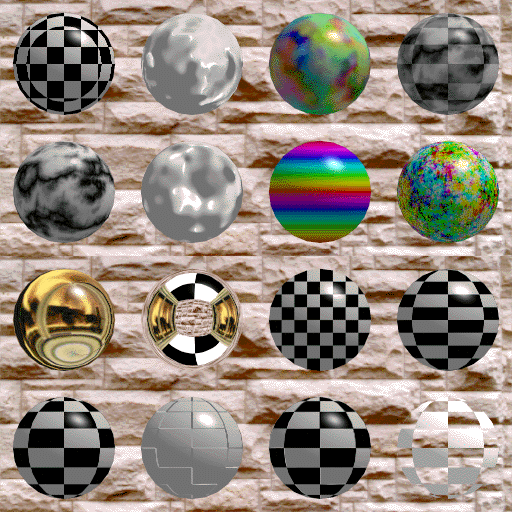
Each sphere in the previous image demonstrates different texturing methods.
The following table describes each sphere, starting from the lower-left
sphere and proceeding to the right then upwards:
Sphere # 1
shows the simplest form of 2d texture mapping. A checkerboard texture
is mapped around a sphere using the sphere's built-in u/v texture
coordinates.
Sphere # 2
demonstrates bump mapping. The same checkerboard texture bitmap is used
to add bumps to the sphere where the texture changes between black and
white (the bumps may not be obvious in the image).
Sphere # 3
combines the texture mapping of Sphere # 1 and the bump mapping of
Sphere # 2 (the bump mapping may not be obvious in the image).
Sphere # 4
demonstrates opacity mapping. The same checkerboard texture bitmap is
used to modulate the opacity of the surface. The sphere is transparent
where the texture image is black and opaque where the texture image is
white.
Sphere # 5
demonstrates spherical environment mapping. A bitmap image of a
fireplace is used to simulate a gold surface.
Sphere # 6
demonstrates cubical environment mapping. The sphere reflects 6 images
that are mapped to the faces of a cube (the sphere shows the fireplace
image, the checkerboard image, and the image used for the background).
Sphere # 7
demonstrates how to use the orthographic texture parameterization
method to add new texture coordinates to an object. In this case the
sphere's built-in u/v texture coordinates have been overridden with new
front-on projected coordinates. Note how the texture appears to be
projected square-on.
Sphere # 8
demonstrates how to use the cylindrical texture parameterization method
to add new texture coordinates to an object. In this case the sphere's
built-in u/v texture coordinates have been overridden with new
cylindrically projected coordinates. Compare this sphere to the
lower-left hand corner sphere (the checker pattern does not get
compressed in the vertical direction for sphere # 8).
Spheres # 9 through # 15
demonstrate 7 different 3D procedural texture functions. These textures
are computed on-the-fly rather than texture mapped from a bitmap image.
Sphere # 16
demonstrates how two (or more) textures can be layered on top of each
other. The first layer is the checkerboard bitmap image and the second
layer is the 3d procedural marble shown in sphere # 9.
 Back to the main screen
Copyright - Sudhir R Kaushik (sudhir@cs.wpi.edu)