Overview of Acceleration Techniques
Ray tracing acceleration techniques can be can be placed into three categories:
- Ones that reduce the average time needed to intersect a ray with the world
- Ones that reduce the total number of rays that need to intersect with the world
- Ones that replace the individual rays with with a more generalized entity
Techniques that reduce the total number of rays that intersect with
the world are often used in conjunction with anti-aliasing techniques
which cast multiple rays for each pixel. The reader is directed to [1]
for an introduction to Adaptive Super-sampling, Stochastic Ray
Tracing, and Statistical Super-sampling as these techniques
are beyond the scope of this presentation.
Techniques that reduce the average time needed to intersect a ray with
the world can then be divided into 2 sub-categories.
- Faster object intersection algorithms
- Fewer object intersections
Faster Object Intersection Algorithms
These algorithms aim at reducing the average cost of testing a ray for
intersection with an object. The predominant feature in these
algorithms is to order the calculations in a way that allows
intermediate tests for intersection to be performed. The tests, based
on the current stage of calculation, are able to determine if the ray
misses the object. If it does no further calculations are needed. Eric
Haines in [1] offers a geometric solution to intersection with a
sphere which has four stages of calculation.
- Find if the ray's origin is outside the sphere.
- Find the closest approach, tca, of the ray with the sphere
- If the ray is outside and points away from the
sphere, the ray must miss the sphere.
- Find the squared distance from the closest approach,
t2hc, to the sphere surface.
- If the value is negative the ray misses
- Using tca & t2hc calculate the time, t, of intersection with the sphere
- t = tca - sqrt(t2hc), origin outside sphere
- t = tca + sqrt(t2hc), origin inside sphere
Fewer Object Intersections
The goal of these techniques is to reduce the number of object
intersection tests for a given ray. These can be broken down into
categories as follows.
- Bounding Volumes
- Spatial Subdivision
- Directional Techniques
- Light Buffer
- Ray Coherence
- Ray Classification
The following is meant as a summary of the above techniques as
presented by James Arvo and David Kirk in [1]. All images are based on
those from [1]
Bounding Volumes
Instead of each ray against every ray test the ray against collection
of objects which are known to be contained within a bounding
volume. If the ray does not hit the bounding volume it cannot hit any
of the objects within. This method lends itself to hierarchical
collections in which the objects within a bounding volume can
themselves be bounding volumes containing ...
Issues: Tightness of Fit vs. Speed of Intersection
Ideally one wants to have a bounding volume that is a tight fit to the
collection of objects within. However, this can often require complex
shapes whose intersection cost rivals that if the objects were
considered individually
Bounding volumes and there effectiveness will be discussed further in
the implementation section
3-D Spatial Subdivision
Non-Uniform & Uniform
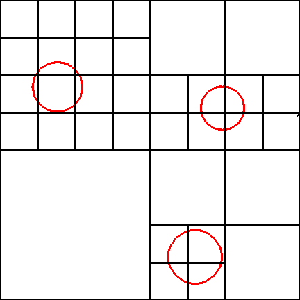
Non-Uniform Subdivision

In Non-Uniform subdivision the world is divided into 8 quadrants, a
check is then made of the number of objects whose surfaces occupy some
portion each quadrant. If the number is greater then some threshold
that quadrant is further subdivided into eight quadrants, etc.. An
octree is used as the data structure for indexing the candidate
objects for each voxel in a hashtable. Tracing a ray involves finding
which voxel the ray originates from, checking it against all the
objects in that voxels candidate list for intersection, if no objects
are hit, determine which voxel the ray passes through next (How?) and
repeat the process.
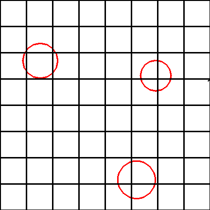
Uniform Subdivision

Uniform subdivision is very much the same except the world is divided
into equal sized voxels Because of this algorithms similar to the
Bresenham line drawing algorithm can be used for quickly determining
which voxel the ray hits next.
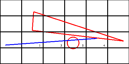
Issues:
- The same ray may test the same object for intersection
multible times. Mailbox?
- Need to make sure the intersection occurs in that voxel

Both of these issues are illustrated above. The triangle will be tested
for intersection with the ray in voxel 2. If a check is not made to see
that the intersection occurs in that voxel the correct intersection
with the sphere will not be found. When the ray enters voxel 3 the
intersection for the triangle should not have to be recalculated. When
ever a ray is intersected with an object the result of that
intersection along with the rays ID is stored in the objects
mailbox. When a object is tested for intersection with a ray
the ray's ID is first tested against the ID in the mailbox. If they
match the result stored in the mailbox can be used avoiding the
recalculation.
Directional Techniques
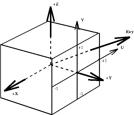
The Directional Cube

A directional cube is an axis aligned cube with side of length 2 at
the origin. The six faces are labeled by there dominant axis +X, -X,
+Y, -Y, +Z, -Z. A ray can be represented as two coordinates (u, v) on
one of these faces. Also the surface of each of the faces can
subdivided (uniform or non-uniform) to define directional pyramids with
the origin at there apex
The Light Buffer
The light buffer is used as a preprocessing step to ray tracing to
speed-up the calculation of shadows. It uses a directional cube
centered at the light source and surface sub-division (of the
directional cube). Each Object in the world is then projected onto
each face of the cube. Candidate lists for each region can be
formed. During ray tracing all that is needed is to determine which
region in which surface the ray passes through, and check it against
the candidate list for that region.
Ray Coherence
Same idea as the light buffer applied to every object in the world. For non-shadowing rays
need to find the closest intersection not just any.
Ray Classification
In three space rays have five degrees of freedom corresponding to the
points R3 x S2 where S2 is the unit sphere in three space. The
algorithm partitions the 5-D space into regions encoded as 5-D
hypercubes and associating a complete list of candidate objects with
each. A hypercube represents a collection of rays with similar
origins and directions. To intersect a ray locate the hypercube that
contains the 5-D equivalent of the ray and test only those objects in
the associated candidate list.
The above presentation is by no means complete. Its purpose was to
demonstrate that there are a variety of techniques available for
improving ray tracer performance. The potential benefit of
implementing any technique should be weighed against the requirements
of the system and the effort needed both in implementation and
maintenance of a more complex system.


