Implementation Strategy and Results
Two strategies were employed in the implementation of an objected
oriented ray tracer. Both of them were aimed at reducing the number of
objects that need to be tested for intersection with a given ray.
Bounding Volumes
The first technique was to use bounding volumes for complex
objects. Because of the object oriented implementation this was a
rather simple matter. Every renderable object is subclassed for an
abstract class GraphicalObject. The GraphicalObject has a
virtual method intersect(Ray). In the case that the object is a
primitive (sphere, cylinder, circle, hyperboloid, ...) this method
will perform the intersection calculation. In a complex object which
is composed of other objects and contained in a bounding volume, the
function will first call the intersection method of the bounding
volume. If this fails intersection failure is returned and none of the
other objects need be tested. If it is found that the bounding volume
is intersected then the intersect method of all the objects that
compose the complex object must be called. Which ever object is found
to have the closest point of intersection is returned along with the
time of intersection. If no objects are found to intersect the ray
failure is returned.
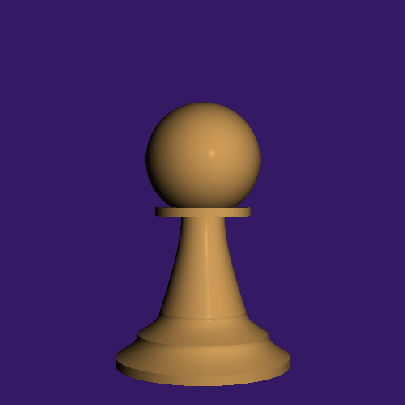
The Above image of a pawn (traced at 500 x 500 pixels) is composed of
6 primitive objects, 2 cylinders, 3 hyperboloids, and 1
sphere. Without a bounding volume the image takes about 65 sec. (59
sec, 67 sec, 69 sec) to trace. If the pawn is treated as a complex
object with a cylinder as a bounding volume, the time to trace it is
reduced to about 35 sec. (34 sec, 34 sec, 38 sec) almost cutting the
rendering time if half.
Spatial Subdivision
The second technique used is a form of
non-uniform spatial subdivision. Instead of breaking the world into
voxels, 4 planes are defined using the observer point and the 4
corners of the view plane.
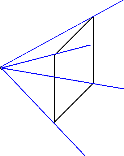
The objects in the world are then tested to determine if any portion
of them is in the viewing area defined by these planes. This is
accomplished with the InView(plane) method of the
GraphicalObject class. It is important to keep this method as simple
as possible. For example the implementation of this method for a
sphere involves displacing the center of the sphere(in world
coordinates) by its radius in the direction of the normal of the plane
and determining which side of the plane this point falls on. Only
those objects that are in view need to be considered for
intersection. If the number of objects is above some threshold amount
the view plane is subdivided and the process repeated on each of the
new "smaller" viewplanes.
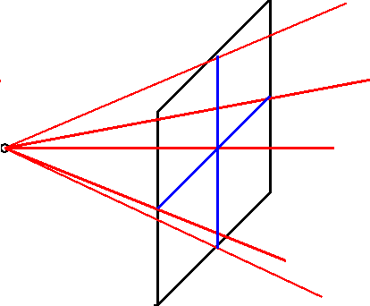
This recursive non-uniform subdivision is handled by threads. Every
time the "viewplane" is subdivided 4 threads are created to process
each of the new viewplanes. Each thread if given a list of objects
that were in view of the larger viewplane as well as which quadrant of
that viewplane it is processing. The quadrant number is needed to keep
the thread from checking the objects against the planes that were part
of the previous viewplanes boundary.
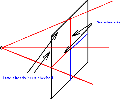
The recursion bottoms out if either the number of objects in view is
below some threshold or if the area of the viewplane is below some
threshold. In this implementation the object threshold was set at 0
(if there are no objects in view set the pixel to the background
color) and the area cutoff was 500 pixels.
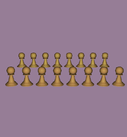
The above image (500 x 500 pixels) of 16 pawns with bounding volumes
takes about 195sec. (190sec & 199sec) to trace without spatial
subdivision. Using the above thresholds the time is reduced to
53sec. (58s, 60s, 55s, 41s) almost 1/4 the execution time.
It should be noted that these timings were performed on a
multiprocessor(2) alpha with kernel supported pthreads and 500M RAM.


