![[Radiosity Image]](images/bld2012.gif) Click here for examples of some beautifully rendered radiosity images.
Click here for examples of some beautifully rendered radiosity images.by Allen Martin
![[Radiosity Image]](images/bld2012.gif) Click here for examples of some beautifully rendered radiosity images.
Click here for examples of some beautifully rendered radiosity images.
 Diffuse
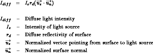
The diffuse component of the Phong model represents reflections that are not directional in nature. Each surface has a diffuse reflectance characteristic that determines how much light is reflected off the surface. The amount of light reflected is independent of the direction that the surface is being viewed from since surfaces that reflect diffusely reflect in all directions equally. The intensity of the diffuse reflection varies only with the cosine of the angle between the surface normal and light source.

 Specular
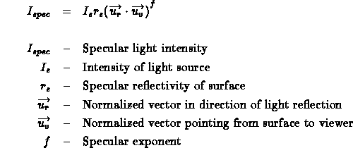
The diffuse component of the Phong model is used to characterize reflections that are highly directional. Examples of this would be bright highlights on a shiny object. Similar to diffuse reflections, each surface has a specular reflection coefficient that determines how much light is reflected off the surface. The intensity of a specular reflection is also proportional to the cosine of the angle between the view direction and the direction the light is reflected in. In addition, there is a specular exponent that determines how quickly the specular highlight drops off as the view angle moves away from the reflection angle.

 Ambient
The ambient component of the Phong model is added to take into account light generated from inter-object reflections. In real environments surfaces that are not directly lit are not completely dark. Light generated by reflections off other diffuse and specular surfaces serves to illuminate these areas. To model this, Phong uses a constant ambient illumination term that when multiplied by the ambient reflectivity of the surface, gives the ambient component of illumination.

The total Phong model is made up of the sum of these three components:

The purpose of radiosity is give an alternative to the Phong model that better approximates the interaction of diffuse surfaces. The radiosity model does not use specular reflections in any way, but there has been some work to attempt to combine radiosity with specular reflection methods [WAL87].
 Demand Driven
Lighting Calculation
This is what is typically used with a z-buffer, raytrace, or painter's algorithm rendering system. The renderer computes the location of a polygon, or what polygon is present at a particular pixel and then needs to know the intensity and/or color to draw that polygon/pixel. The lighting calculation is done as the last step and is driven by the demand to know what color/intensity to display on the screen.
 Data Driven
Lighting Calculation
Radiosity uses a data driven approach to lighting calculation. Instead of computing the lighting as the last step in the rendering process, it is done beforehand. Certain surfaces in the scene are given initial intensities, and the effect they have on other surfaces in the scene is computed in an iterative manner. This is done independently of the location of the viewer. The presence of these lit surfaces in the model is what drives the computation of the system.
The radiosity method is based upon a simple model of energy transfer. At each surface in a model the amount of energy that is given off is comprised of the energy that the surface emits internally, plus the amount of energy that is reflected off the surface. The amount of energy that is reflected off the surface can be further characterized by the product of the amount of energy incident on the surface and a reflectivity constant of the surface.

The radiosity of a surface is the energy that is given off. This is what is used to determine the intensity of the surface and is what is being solved for. The amount of light emitted from a surface must be specified as a parameter in the model, just as in traditional lighting methods where the location and intensity of light sources must be specified. The reflectivity of the surface must also be specified in the model, just as in traditional lighting methods. The only unknown in the equation is the amount of incident light hitting the surface. This can be found by summing for all other surfaces the amount of energy that they contribute to this surface.

The form factor in the above equation is defined to be the fraction of energy that leaves surface i and lands on surface j, and is therefore a number in the range (0..1). This form factor can be computed via analytical means, or through a geometric analog. See [COH85] for more information on form factor computation.
The radiosity equation now looks like this:

![[radiosity matrix]](images/rad_matrix.gif)
This matrix has two interesting properties: it is diagonally dominant and is therefore guaranteed to converge when using Gauss Seidel iteration, and the upper right of the matrix is computable from the lower left [GOR84]. Alternate methods for computing the solution of this matrix have been proposed by Cohen et al. [COH88]. Their alterations allow for a faster convergence towards the correct solution than simple Gauss Seidel iteration.
 1 - Generate Model
 2 - Compute Form
Factors
 3 - Solve
Radiosity Matrix
 4 - Render
It is important to note that when rendering a radiosity scene, changing parameters does not require a restart from step 1. In fact, only if the geometry of the model is changed must the system start over from step 1. If the lighting or reflectance parameters of the scene are modified the system may start over from step 3. If the view parameters are changed, the system must merely re-render the scene (step 4).


Allen Martin / amartin@cs.wpi.edu