Free Form Deformation and Extended Free Form Deformation
Carl Shimer
Advanced Topics in Computer Graphics
- Introduction
Free Form Deformation (FFD) is part of the computer graphics literature on soft objects. The definition of a soft object is an object that can be deformed by the user or during the process of animation. Soft object deformation is used for many purposes:
- Shape distortion to highlight dynamic interaction with the environment
For instance, an animator may want to create a basketball that will deform when it bounces on the ground. Another use would be to deform the shape of a car during a collision in a racing simulation.
- Realistic deformation of an object that has a highly elastic and flexible shape. Examples include the facial expressions, motion of the human body, and cartoon animation. In movies like Luxo Jr. and Toy Story, the character shapes are deformed when they walk, talk, or hit another object.
Deformation of an object occurs by moving the vertices of a polygonal object or the control points of a parametric curve. Deformation of polygonal objects will not be discussed in this presentation. Successful deformation of a polygonal object requires that there be a sufficient number of polygons in the object. If the polygon resolution is low, deformations give rise to a degradation in silhouette edge aliasing[1].
- Mathematical background
- Parametric representation of objects
The easiest type of object to deform is one that uses a parametric representation. In order to change the shape of a parametric curve, one of the control points must be moved. However, the deformed curve has the same resolution as the undeformed original curve and is immune to the degradation of polygonal objects. Of course, rendering a parametric curve is more challenging that rendering a polygonal shape.
2. Bezier Curves
A Bezier curve of degree n can be defined in terms of a set of control points pi (i=0,1,2... n). In essence, each control point influences the shape of the curve. The curve is defined by the following equation:
Basically, this is a summation of the blending function Bi,u(u) and the control point pi. The blending function is called a Berstein polynomial and is defined by the equation:
where nCi is the binomial coefficient:

Note that nCi and be precomputed and plugged in to the Berstein polynomial. To see an interactive example of a bezier curve, try this site.
3. Tricubic Bezier Hyperpatch
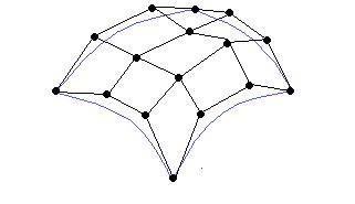
A cubic bezier curve is essentially the basic unit of a cubic bezier patch. Note in the image below, there are a collection of bezier curves that form the bezier patch.
A cubic bezier patch is defined by the following equation. As you will see, it is simply an extension of a bezier curve.
Finally, a Tricubic Bezier Hyperpatch is defined by the following equation:
Why have we reviewed this math? Simply because hyperpatches are the building blocks of a free form deformation block. The formula for the Hyperpatch is used to calculate the new deformed point of an object inside an FFD lattice.
3. Free Form Deformation
The technique of Free Form Deformation (FFD) was developed by Parry and Sederberg in [2]. Previously to the development of FFD, all deformations had to performed directly on an object. However, the FFD technique embeds an object in a space that is than deformed[2]. The most comonly used analogy for a FFD is to consider an object embedded in a parallelpiped of clear, flexible plastic. If the lattice structure is deformed, the object inside the lattice will also be deformed.
The lattice structure is composed of tricubic Bezier hyperpatches. A hyperpatch is specified by a three-dimensional grid of 64 control points pijk and defines a volume of space parametrized by the three parameters u,v, and n where 0<u,v,n<1. An FFD block a rectangular volume where each face is a hyperpatch. Let the the three sides be represented by the vectors (S,T< and U). We define the FFD block to be an array of (3l+1) * (3m+1) * (3n+1) hyperpatches[1]. This is essentially a stack of l ´ m ´ n hyperpatches.
Sederberg outlines the following algorithm for creating a Free Form Deformation:
- Determine s,t,u for points interior to the hyperpatch
To do this, we must first set up a local parametric coordinate system inside the FFD block called the lattice space. The lattice space is given by: X(s,t,u) = X0 + sS + tT + uU. X0 is the origin of the local coordinate system and S, T, and U lie along the edges of the FFD block. Note that for any point interior to the lattice 0<s<1, 0<t<1, and 0<u<1. Next, the control points on the lattice are defined by the following equation:
- Deform hyperpatch by moving control points
Control points can be interactively moved by the user or automatically generated by an animation routine. For instance, if the user wants to deform the shape of a teapot, he could drag one of the control points farther away to stretch the teapot. Most FFD tools allow the user to interactively change the control points and immediately see the deformation of the object inside the lattice.
- Calculate deformed positions of points from s,t,u.
Basically, this is a translation of a vertice in a polygonal representation or a control point in a parametric representation from the lattice space to the object space. Given the lattice space coordinates (s,t,u) of the control point or vertice, we find the relevant hyperpatch within which it is located and convert to the the local (u,v, w) coordinate system of the hyperpatch. To find the hyperpatch, we need to get get the integer component of l´ s, m´ t, n´ u which store as is,it,iu. These three integer components specify the location of the hyperpatch within the FFD block. We then get our u,v,w coordinates from the equation (u,v,w) = (ls - is, mt - it, nu - iu). Finally we perform the hardest part of calculating the position of the deforming vertice or control point: we plug the u,v,w values back into the hyperpatch formula:
Multiple FFD blocks can be chained together to enhance the deformation of an object. In order for the deformation to be continuous, I.E. smooth curves without any breaks, the control points where the two FFD blocks are joined can not be deformed. Finally, if the FFD mesh is comparable in complexity to the object it is deforming, than object degradation can result.
Examples:
Car animation
Animated Teapot
Teapot and glass
- References
1. Watt, Alan and Watt, Mark. Advanced Animation and Rendering Techniques. ACM Press, New York, New York. p. 395-413.
2. Sederberg, Thomas and Parry, Scott. "Free Form Deformation of Solid Geometric Models." SIGGRAPH, Association of Computing Machinery. Volume 20, Number 4, 1986. 151-159.
3. Coquillart, Sabine. "Extended Free-Form Deformation: A Scupting Tool for 3D Geometric Modeling".
![[Return to CS563 '97 talks list]](/images/back.gif)