
Last modified: 02/04/97
Acknowledgements
Much of the organization and content of this presentation came from the following sources: Mark Segal and Kurt Akeley's white paper on OpenGL, David Quarrie's OpenGL overview, and SGI's OpenGL data sheet.
OpenGL is a hardware-independent, operating system independent, vendor neutral graphics API specification. Many vendors provide implementations of this specification for a variety of hardware platforms. Bindings exist primarily for the C programming language, but bindings are also available for Fortran and Ada.
OpenGL has been designed using a client/server paradigm, allowing the client application and the graphics server controlling the display hardware to exist on the same or separate machines. The network is transparent to the application.
OpenGL is window system independent, and therefore contains no windowing operations or mechanisms for user input. Also, OpenGL does not provide direct support for complex geometrical shapes, such as cubes or spheres. These must be built up from supported primitives.
Some features of OpenGL include the following:
Also available with OpenGL are the following three libraries:
OpenGL is defined and released by the OpenGL Architecture Review Board (ARB). The ARB consists of representatives from industry, including DEC, E&S, H-P, IBM, Intel, Intergraph, Microsoft, SGI, and Sun. The ARB oversees the administration of the OpenGL Specification and Conformance Test Suite.
The OpenGL architecture is structured as a state-based pipeline. Below is a simplified diagram of this pipeline. Commands enter the pipeline from the left.
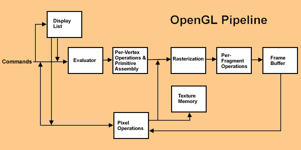
Commands may either be accumulated in display lists, or processed immediately through the pipeline. Display lists allow for greater optimization and command reuse, but not all commands can be put in display lists.
The first stage in the pipeline is the evaluator. This stage effectively takes any polynomial evaluator commands and evaluates them into their corresponding vertex and attribute commands.
The second stage is the per-vertex operations, including transformations, lighting, primitive assembly, clipping, projection, and viewport mapping.
The third stage is rasterization. This stage produces fragments, which are series of framebuffer addresses and values, from the viewport-mapped primitives as well as bitmaps and pixel rectangles.
The fourth stage is the per-fragment operations. Before fragments go to the framebuffer, they may be subjected to a series of conditional tests and modifications, such as blending or z-buffering.
Parts of the framebuffer may be fed back into the pipeline as pixel rectangles. Texture memory may be used in the rasterization process when texture mapping is enabled.
Most objects (with the exception of pixel rectangles and bitmaps), use Begin/End primitives. Each Begin/End primitive contains a series of vertex data, and may optionally contain normals, texture coordinates, colors, edge flags, and material properties.
There are ten primitive types, as follows:
| Points | individual points | 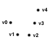 |
| Lines | pairs of vertices interpreted as individual line segments | 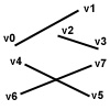 |
| Polygon | boundary of a simple, convex polygon | 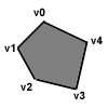 |
| Triangles | triples of vertices interpreted as triangles | 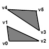 |
| Quads | quadruples of vertices interpreted as four-sided polygons | 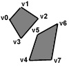 |
| Line Strip | series of connected line segments | 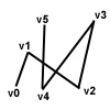 |
| Line Loop | same as above, with a segment added between last and first vertices | 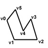 |
| Triangle Strip | linked strip of triangles | 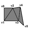 |
| Triangle Fan | linked fan of triangles | 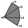 |
| Quad Strip | linked strip of quadrilaterals | 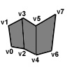 |
Vertices may be specified in 2D, 3D, or 4D. 2D coordinates are promoted to 3D by assigning a Z value of zero. 4D homogeneous coordinates are reduced to 3D by dividing x, y, and z by the w coordinate (if non-zero).
Optional vertex attributes are picked up from state if not specified per-vertex. The normal is a 3D vector perpendicular to the surface being described, and is used during lighting calculations. The color may be an RGBA value, or a Color Index, depending on the visual type of the window. Texture coordinates determine the mapping of a texture onto the vertex, and may be specified with 1, 2, 3, or 4 parameters. Edge flags are used to specify if the vertex is on a boundary of a surface. Material properties specify such things as reflectance, ambience, etc, and are used for lighting calculations.
These vertex and attribute commands, as well as many other OpenGL commands, accept arguments either explicitely or through pointers. They also accept a variety of data types as arguments, such as ints, floats, doubles, bytes, unsigned ints and bytes, etc.
Commands not associated with primitives are not allowed within Begin/End blocks. This allows increased optimization of primitive processing.
The model-view matrix, texture matrix, and projection matrix each affect the vertex and its attributes, and may be easily manipulated via transformations such as rotation, scaling, and translation.
Lighting parameters, such as material properties, light source properties, and lighting model parameters affect lighting on a per-vertex basis.
Once a primitive has been assembled, it is subject to arbitrary clipping via user definable clip planes. An OpenGL implementation must provide at least six, and they may be turned on and off independently by the user.
Points are either clipped in our out, depending on whether they fall inside or outside the half-space defined by the clip planes. Lines and polygons, however, may either be 100% clipped, 100% unclipped, or they may fall partially within the clip space. In this latter case, new vertices are automatically place on the clip boundary between pre-existing vertices. Vertex attributes are interpolated.
After clipping, vertices are transformed by the projection matrix (either perspective or orthagonal), and then clipped to the frustum (view space), following the same process as above. Finally, the vertices are mapped to the viewport (screen space).
Rasterization converts the above viewport-mapped primitives into fragments. Fragments consist of pixel location in framebuffer, color, texture coordinates, and depth (z buffer). Depending on the shading mode, vertex attributes are either interpolated across the primitive to all fragments (smooth shading), or all fragments are assigned the same values based on one vertex's attributes (flat shading).
Rasterization is affected by the point and line widths, the line stipple sequence, and the polygon stipple pattern. Antialiasing may be enabled or disabled for each primitive type. If enabled, the alpha color value (if in RGBA mode) or color index (if in CI mode) are modified to reflect sub-pixel coverage.
Pixel rectangles and bitmaps are also rasterized, but they bypass the lighting and geometrical transformations. They are groups of values heading for the framebuffer. They can be scaled, offset, and mapped via lookup tables. The rasterization process produces a rectangle of fragments at a location controlled by the current raster position state variable. The size may be affected by the pixel zoom setting.
Bitmaps are similar to pixel rectangles, but the data is binary, only producing fragments when on. This is useful for drawing text in 3D space as part of a scene.
When enabled, a fragment's texture coordinates index a texture image, generating a texel. The texel may represent just intensity, transparancy, or full RGBA color. The texel modifies the fragment's color based on the current texture environment, which can either be decal, blend, or modulate mode.
The texture being mapped may be filtered by a variety of texture filters, each a trade-off of quality versus computational cost. Mipmaps may be specified, allowing smaller representations of the texture to be used when the projected size of the primitive is small.
After texturing, a fog function may be applied to the fragments. This is a blend of the fragment's color with a constant, user-specifiable fog color. The blend is based on the distance of the viewer from the fragment, and may either be linear (depth curing) or exponential (atmospheric affects).
Fragments produced by rasterization go to the framebuffer where they may be displayed. The framebuffer is a rectangular array of n bitplanes. The bitplanes are organized into several logical buffers -- Color, Depth, Stencil, and Accumulation.
The color buffer contains the fragment's color info.
The depth buffer contains the fragment's depth info, typically used for z-buffering hidden surface removal.
The stencil buffer can be associated with fragments that pass the conditional tests described below and make it into the framebuffer. It can be useful for multiple-pass algorithms.
The accumulation buffer is also used for multiple-pass algorithms. It can average the values stored in the color buffer. Full-screen antialiasing can be achieved by jittering the viewpoint. Depth of Field can be achieved by jittering the view angle. Motion blur can be achieved by stepping the scene in time.
Stereo and double-buffering may be supported under OpenGL, depending on the implementation. These would further divide the framebuffer into up to 4 sections -- front and back buffer, left and right. Other auxiliary buffers may be available on some implementations. Any buffers may be individually enabled or disabled for writing. The depths and availabilities of buffers may vary, but must meet the minimum requirement of OpenGL. Each buffer may be individually cleared to a specified value.
Before being placed into the framebuffer, each fragment may be subjected to a series of tests and modifications, each of which may be individually enabled, disabled, and controlled. These include stencil test, depth test, and blending.
The stencil test compares the value in the stencil buffer associated with the fragment with a reference value. If successful, the stencil value may be updated and the fragment proceeds to the next test. If it fails, the fragment is discarded, and the stencil value may be updated with another value.
The depth test is similar. It compares the fragment's depth with that currently in the depth buffer. If successful, the depth buffer is updated and the fragment proceeds to the next test. Otherwise, the fragment is discarded and the depth buffer is unchanged.
Blending mixes the fragment's color with the color already in the color buffer based on some blend function. This is used for antialiasing and transparency.
Evaluators allow the specification of polynomial functions of 1 or 2 variables which may be used to determine a primitive's vertex coordinates, normal coordinates, texture coordinates, and/or color. A polynomial map based on a Bezier basis may be specified for any of these attributes individually.
Evaluators may either be used within primitives (generating individual vertices) or outside of primitives (generating entire primitives).
Display lists encapsulate a group of commands so that they may be later issued as many times as desired simply by calling the list by name. This allows increased optimization, server-side command caching, and simplified user programming. Display lists may be redefined, but may not be edited. They can be nested, however.
So far we have discussed OpenGL's render mode, by which primitives are rendered to the framebuffer. There are two other modes -- feedback and selection.
In feedback mode, primitives are intercepted after processing but before rasterization. It returns info about the primitives, such as vertex coordinates, texture coordinates, and color. This is useful for rendering to vector devices, such as pen plotters.
In selection mode, OpenGL returns a "hit" whenever a clipped primitive lies within the view frustum. This can be useful for picking primitives via the cursor.
Nearly all of OpenGL state may be queried. Most attributes may be pushed and popped from stacks to quickly go back and forth between state configurations.
OpenGL is a fully functional primitive-level API that allows the programmer to efficiently address and take advantage of graphics hardware. Many high-level libraries and applications make use of OpenGL due to its performance, ease of programming, extensibility, and widespread support.
OpenGL® is a registered trademark of Silicon Graphics, Inc.