CS 110X Feb 26 2014 : LAB SIX
Give me a fulcrum and I shall move the world
Archimedes
1 Arduino Project
The instructions here are intended to fully describe the sequence of steps you need to complete the lab. There are not enough Arduino boards to go around, so everyone must "pair up" and work in teams (you don’t have to work with your programming partner; just someone in the lab time slot). Be sure to sign the "sign in sheets" to receive credit for the lab when you leave.
Create a folder "LAB6" in which you will place all files in this lab. This folder will be known as the LabFolder for the duration of this lab. For example, create it in your "My Documents" or "Desktop" location on the lab PC.
1.1 Physical Materials
You should have a lab kit that consists of:
Arduino Uno Hardware
White USB A-to-B cable
Magnetic Card Reader
five wires (2 green, 3 yellow)
plastic bag on which to place all material
1.2 Arduino
Launch the Arduino 1.0.2 Development Environment (you should find it under Start Menu | All Programs | Arduino.
Download the following file (CardReader_Python.ino) and store it in the LabFolder.
Now within the Arduino editor, open the CardReader_Python.ino file; you will be prompted:
The file "CardReader_Python.ino" needs to be inside a sketch folder named "CardReader_Python.ino". Create this folder, move the file, and continue?
Select OK and continue.
1.2.1 Connecting Arduino Board
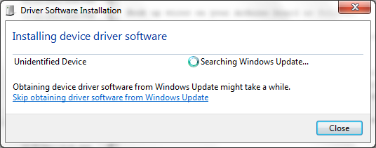
You will now connect the Arduino to your computer. Use the white USB A-to-B cable to connect the Arduino board with the computer. When you do so, Windows will try to install the device driver software. This will take up to a minute. Of course, if someone has already run this lab, this step will be skipped.
When you get to the the "Ready to use" screen, be sure to write down which COM port was used for the installation.
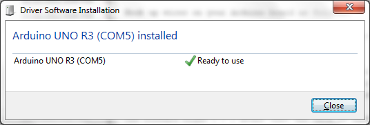
For example, it could be COM4 or COM5. Close the window.
You can review which port your Arduino board is using by selecting Start Menu | Devices and Printers. You will see Arduino Uno R3 appear in this list under "Unspecified" and the COM port used will appear there as well.
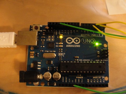
There is a small LED light on the board labeled "ON" which should be showing a steady green light. This signals that your board has power.
1.2.2 Magnetic Card Reader
Your Magnetic card reader has five wires coming out. As best as I can determine, these wires are:
Black – Ground connection
Blue – Data1 wire
Green – CardPresent wire
Yellow – Strobe wire
Red – +5V power
You will naturally want to connect the magnetic card reader to your Arduino board. It would be nice if I could have found some equally colored jumper cables, but, Alas! I only have three colors.
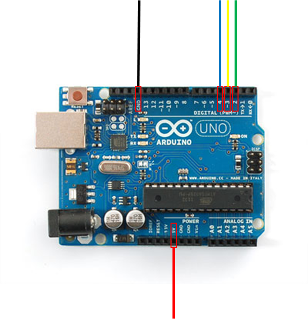
Look at the following diagram for the resulting connections that you are to make using these jumper wires. Don’t worry, you won’t electrocute yourself! But don’t damage these boards, please!
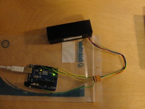
The end result is shown below, namely, where the different colored wires are to be connected onto the Arduino board.
Now, as mentioned earlier, we don’t have the right color matches. But you don’t need to worry about that. Look at the cable connecting to the magnetic card reader. You will see in the plastic attachment that there are five holes into which you can insert the jumper wire connections. These wires are firm enough to make a solid connection.
Make the following connections.
Use two green wires to connect Power (RED) and Ground (BLACK). Note that the Ground seat is the fourth hole from the left on the top, and the +5V seat is the fifth hole from the left on the bottom.
Use two yellow wires to connect the Blue (Data1 wire) to the pin seat number 4, and the Green (CardPresent wire) to pin seat number 2.
Use final yellow wire to connect the yellow (Strobe wire) to pin seat number 3.
Double check the connections, especially the colorings from the magnetic card reader because all of the jumper wires are yellow and green.
1.2.3 Downloading the code onto the Arduino
In the Arduino IDE under the Tools menu, make sure that Tools | Board is set to the Arduino Uno. Also make sure that Tools | Serial Port is set to the same COM port that was discovered earlier during the installation.
Now in the Arduino IDE, select File | Upload (or Control-U). You will notice that in the Arduino IDE it says that it is compiling, when that is done, quickly look at the Arduino board itself. There will be two rapidly flashing IDEs labaled "TX" (transmitting) and "RX" (receiving). This activity demonstrates that data is being moved onto the board.
When this process is done, there should be no errors in the Arduino IDE console and the LED labeled "L" on the board (right next to the Arduino infinity logo) shows a steady yellow, telling us that the board is ready.
If you get here and you don’t witness this behavior, then unplug the White USB cable from the computer, wait a second, and reinsert the USB plug. This resets the Arduino board; then you can go back to the Arduino IDE and attempt to upload the code once more. If errors continue, then it is possible that your board/configuration is defective – tell the TA; you will still get credit for the lab.
1.2.4 Demonstrate Working Arduino Code
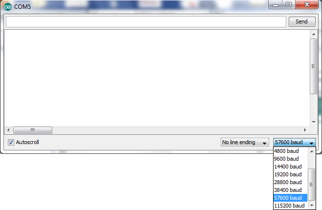
Select the Tools | Serial Monitor menu item and a window appears which records the serial data being sent from the Arduino board. At the lower right corner. Make sure that you change the baud rate to 57600 baud.
Once you do this, you will see "OK" appear in the Serial Monitor output window.
You are now ready to test out the Arduino project. Take any magnetic striped card from your wallet (your WPI ID card will work). Now carefully hold the magnetic card reader device so the slot is facing you and the wires emanating from the reader are at the bottom. You should see a subtle "downward arrow" on the reader itself, which tells you that you need to swipe the card from top to bottom.
Hold your card so the magnetic stripe is "down and on the right side". That is, the front of the card should be on the left.
Now, Swipe!
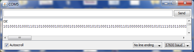
The above shows what should happen on a successful swipe. A sequence of zeros and ones should appear.
You can swipe any number of cards, and the reader is reasonably flexible regarding how fast you need to swipe.
Please make sure that you close the Serial Monitor window before you continue. Otherwise you will be unable to have your Python lab connect to the Arduino board!
Congratulations! You are done with step 1 of this lab! You no longer have to deal with the Arduino hardware. Now it is time to write a Python program to process these zeros and one values.
1.3 Get Python Started
Download the following file (lab_6.py) and store it in the LabFolder you created at the start of this lab.
You need to ensure that the serial Python module is installed. To do this, you need to bring up a DOS CMD window. Click on the start menu button in the lower left corner of the Windows Desktop and where it says "search programs and files" type "CMD.exe" without the quotes and press return. A DOS prompt window will appear. Type the command easy_install pyserial and press return.
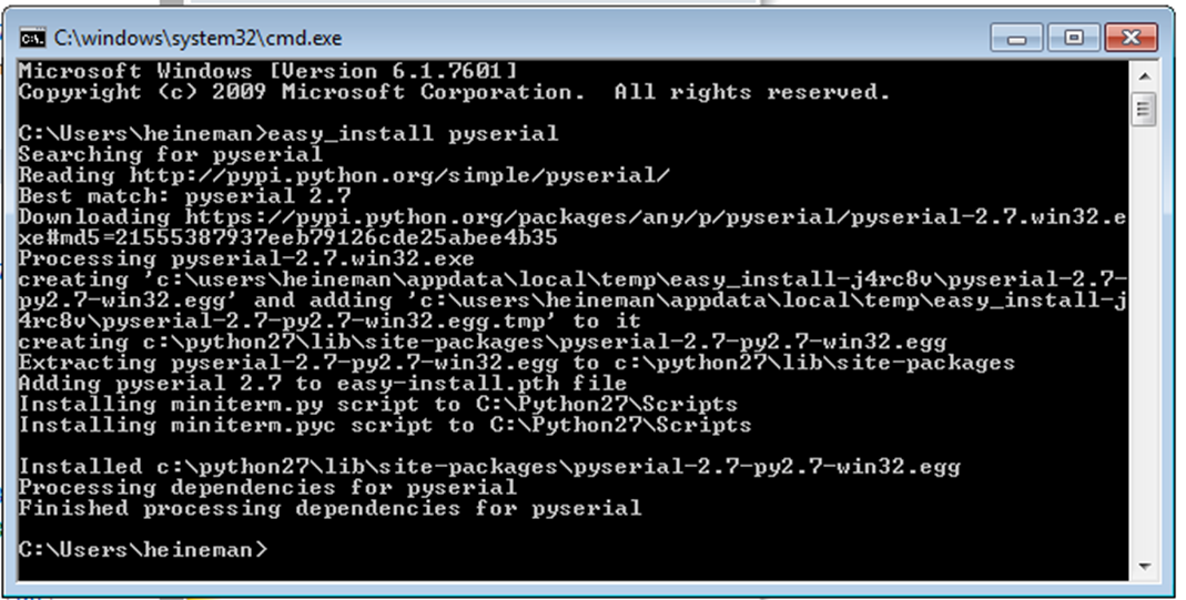
This will properly install the requisite serial module for you. If you have an IDLE instance already running, please exit it now so this change will become available.
Launch the IDLE Python editor and open up the lab_6.py file for editing. This file contains three functions.
convert(bits) – This is the function you are to write.
convertSevenBits(bits) – converts 7-bit encoding into character.
readCard() – main method to read data from a card.
Scroll down to see the the readCard method which initializes the communication to the serial connection:
# open communication to Arduino, choose same baudrate as Arduino SW out = serial.Serial("COM5", baudrate=57600)
If the installed Arduino board appears on a different COM port (e.g, COM6) then you must change the above string to match that port exactly. Note that the baudrate must remain 57600 otherwise your Python code won’t properly communicate with the Arduino embedded software that you uploaded earlier.
1.4 Python Program to read
Once you load up the module, invoke the readCard() function. You will likely encounter a SerialException stating that Access is denied. This occurs because the Serial Monitor you opened earlier is still active. Close that window. Now relaunch the readCard() method.
Note that Python now says "READY. now waiting for card to be swiped."
Carefully, as before, swipe a card and you will now see that Python retrieves the string of zeros and ones that had appeared in the Serial Monitor.
You will also see:
INSERT CODE HERE
NOT_YET_WRITTEN
When you complete the lab, the contents of the swiped card should be output to the screen. You will know when you get it right.
For example, here is the sample output from a gift card I have in my wallet. Would you care to guess what company it is for?
%B6010566047137505^DUNKINREDSOX/VL^25010004000060036000?L
Your job, now, is to complete the convert(bits) method. Read the documentation and plan your approach.
1.5 Troubleshooting Card Reader Issues
The most common problem you will encounter is something like the following. Let’s say you start writing the convert(bits) function, but the code looks as follows:
def convert(bits): """ documentation ... """ return val
That is, it returns a variable that has not yet been defined. Type it in, and reload your Python module. Now run readCard().
Traceback (most recent call last): File "<pyshell#2>", line 1, in <module> readCard() File "C:\Users\Laptop\Desktop\LAB6\lab_6.py", line 97, in readCard print (convert(swipe)) File "C:\Users\Laptop\Desktop\LAB6\lab_6.py", line 33, in convert print val NameError: global name ’val’ is not defined
Now quickly type in readCard() again:
Traceback (most recent call last): File "<pyshell#7>", line 1, in <module> readCard() File "C:\Users\Laptop\Desktop\LAB6\lab_6.py", line 82, in readCard out = serial.Serial("COM5", baudrate=57600) File "C:\Python27\lib\site-packages\pyserial-2.6-py2.7.egg\serial\serialwin32.py", line 31, in __init__ SerialBase.__init__(self, *args, **kwargs) File "C:\Python27\lib\site-packages\pyserial-2.6-py2.7.egg\serial\serialutil.py", line 261, in __init__ self.open() File "C:\Python27\lib\site-packages\pyserial-2.6-py2.7.egg\serial\serialwin32.py", line 59, in open raise SerialException("could not open port %s: %s" % (self.portstr, ctypes.WinError())) SerialException: could not open port COM5: [Error 5] Access is denied.
If you see this error repeatedly when you call readCard() then you need only unplug the USB cable from the computer, wait a second, and plug it back in; this action will power-cycle the Arduino hardware to its initial state.
1.6 What To Do When You Are Done
Disconnect the USB cable from the computer. Detach all wires and return to the plastic pouch in which they were originally stored. Place the Arduino back into its box and put it and the magnetic card reader back in the box as you found it (the magnetic card reader conveniently fits in the box, underneath the cardboard seating for the Arduino board). Give the set back to the TA.
To receive credit for the lab, you need to return the kit to the TA and then sign the attendance form.
1.7 Version : 2014/02/25
(c) 2014, George Heineman