Interference
by Chuck Moidel
Introduction to Light
Light is not an easy thing to define
or model. Sometimes it exhibits the properties of a particle and other times it
exhibits the properties of a wave. This is known as the wave/particle duality
of light and has been the source of much philosophizing in physics. In computer
graphics, we typically take a pragmatic course and treat light exclusively as a
collection of particles (Glassner 2000). We treat light as a particle because
the particle, or photon, interpretation has simpler and more intuitive
mathematics. This translates into programs that are less computationally
expensive and run faster. This is why a majority of rendering algorithms are
photon based. The particle interpretation is usually a good choice because it
covers almost all of the normal phenomena associated with light. However, one
of the most important phenomena not described by the particle model is
interference.
Introduction to Interference
|
Colors from paints or dyes, also known as
absorptive pigmentary coloration, is but a single class of color producing
phenomena (Gondek 1994). Colors that are produced entirely by optical
effects of surface geometry are termed structural colors. One example of a
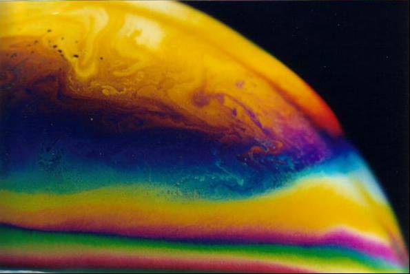
structural color is the color exhibited by thin film interference.
Interference, which causes the swirling colors in bubbles and oil, is a
direct result of the wave nature of light. Since interference is caused by
interacting light waves, to better understand interference, it is important
to understand the properties of both light and waves in general. |
|
 |
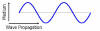
Waves
|
Waves can be categorized as one of two
types based on their behavior - transverse or longitudinal. A transverse wave is
a wave in which the motion of the medium is perpendicular to the motion of the
wave. In other words the disturbance is perpendicular to the wave's direction of
propagation. Waves in water, for example, are mostly transverse. The water moves
up and down while the wave travels over the surface of the water. Sound waves,
on the other hand, are longitudinal. The sound wave's disturbance moves in the
same direction as the wave's propagation. We will now discuss the equations for
representing transverse waves.
|
|
 |
Consider a transverse wave traveling
along an “ideal” string in the x direction. An “ideal” string is one in
which the disturbance keeps its form as it travels. This means that friction and
energy dissipation are ignored. The coordinate y indicates the transverse
displacement of a particular point on the string at position x and time t.
If f is a
function that describes the shape of the wave at time 0, then at time t
the waveform must still be described by f. This is because we assumed
that the shape does not change as the wave travels. Moving in the positive x
direction at speed v for some time t, the wave will travel a
distance vt. If we follow the motion of P, a particular part (or phase)
of the wave, since the wave keeps its shape as it travels, the value yp
must not change. From the equation, this is only possible if the x coordinate of
P increases as t increases in such as way as x-vt remains
constant. This is true for any location on the waveform and for all time t.
x-vt = constant

Now consider a sine wave traveling along
an “ideal” string in the x direction. The coordinate ymax
indicates the maximum displacement or amplitude of the sine curve and λ is
the wavelength. The displacement y has the same value at any x as it does
at x+λ, x+2λ, etc. Wavelength (in meters) equals velocity (in meters/second)
times period T (in seconds).
If the displacement y doesn’t equal zero at position x = 0
at time t = 0 then we need to add a phase constant.

Phase shift in space:
Phase shift in time:
Superposition and Interference
|
The principle of superposition states
that when several waves combine at a point, the displacement of any particle
at any given time is simply the vector sum of the displacements that each
individual wave acting alone would give it (Resnick 1992). For some time t
and position x,
y(x,t)
= y1(x,t) + y2(x,t)
This is why two or more waves can travel simultaneously
through the same region of space independently of one another.
When two or more waves combine at a particular point, they are said
to interfere, and the phenomenon is called interference. Consider two
transverse sinusoidal waves of equal amplitude and wavelength, which travel
in the x direction with the same speed. If the two waves are exactly in
phase, the resulting wave has twice the amplitude. This is called complete
constructive interference and there is reinforcement at every point. If the
two waves are only slightly out of phase, the resulting wave has close to
twice the amplitude. This is called partial constructive interference. If
the two waves differ in phase by π, then the
resulting wave has an amplitude of 0. This is called complete deconstructive
interference and there is cancellation at every point. If the two waves
differ in phase by close to π, then the resulting
wave has a very small amplitude. This is called partial deconstructive
interference. |
|
 |
Given the equations for two waves y1 and y2:
Using the principle of superposition:
Using the trig identity for the sum of sines:

The above equation becomes:

Light Interference
Light interference is an optical
phenomenon resulting from coherent superposition between lights (Sun 1999).
Since light interference relies on full spectral information, a purely color
based approach (such as RGB) will not suffice. Most light interference effects
observed in nature result from thin films or layers of thickness below 1 µm. Thin film interference, or more generally, amplitude splitting interference,
occurs when a wave is divided through reflection and transmission, and later
recombines. Light interference can occur on both the reflection side and the
transmission side of the film. Exiting rays that share the same direction of
propagation to within a small tolerance have the potential to interfere since
they having different optical path lengths. According to the Fresnel-Arago laws,
interference may be produced in the case where components of electric fields
share the same plane of polarization (Gondek 1994). However, electric fields
originating from different incoherent field of natural light never produce
visible interference and must be treated independently. This means that two
light rays from the same light source have the potential to interfere but two
light rays from different light sources do not.
In the image above, interference occurs
between rays 4 and 5 (reflection) and between rays 6 and 7 (transmission). The
propagation from 2 to 5 has an extra path inside the film compared to the
propagation from 1 to 4.
|
 |
 |
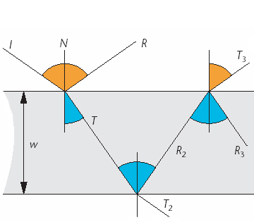
The figure above represents a little
section of soap film from a bubble. A light beam I strikes the upper surface.
Some of that light is reflected in the direction R while the rest is transmitted
into the film in the direction T. On the bottom of the film, some light passes
into the inside of the bubble in direction T2, while the rest is
bounced upward in direction R2. This light hits the top of the film,
where some is reflected back into the film in direction R3, while the
rest comes back into the air in direction T3. T3 is
parallel to direction R, so the light traveling on R is going to interact with
the light on T3. The resulting combined light will depend on the
wavelength and phase of each constituent wave. Assume the light along I has
wavelength λ, the film has thickness w, and the index of refraction of the
film is η (about 1.4 for soap film). The incident angle between I and the normal
N is θi. The light that travels through the film and exits parallel
to R will be phase-shifted with respect to the light that simply reflected off
the surface. The phase difference between these two waves will determine whether
they reinforce or cancel each other, entirely or partly. The phase difference
between the light on R and the light on T3 consists of two
components, the extra distance traveled on the longer path and the optical phase
shift at the interface between the two materials.
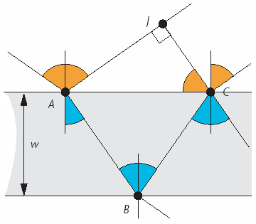
The extra distance can be calculated by using the equations
below. By finding the total difference in distance taken by the two beams
and dividing that by the wavelength, we can determine how much of a cycle the
light will pass through traveling in the film (Glassner 2000).
Beam 1 travels
from A to J.
Beam 2 travels A to B to C
Geometric Difference = |AB|+|BC|-|AJ|
By finding this difference and converting
it to the number of radians it represents for that wavelength, we’ll get the
phase difference. However, light travels more slowly in a medium that is denser
than air, such as soapy water. Because it travels more slowly, it passes
through more of its cycle when going through the water than when passing through
an equivalent distance of air. To model this effect, we multiply the distance
traveled in the dense medium by the medium’s index of refraction. This scales up
the length to the equivalent distance the wave would have covered in air in the
same amount of time.
The phase
difference is d=η(|AB|+|BC|)-|AJ|
Using the following equations:
We get:
We will now calculate the phase
difference. When light moves from one medium to a medium of higher
refractive index, it undergoes a phase shift equal to half its wavelength (Glassner
2000). One needs to add λ/2 to the difference
calculated on the previous page because the light went from air to soap at point
A. To computer the phase change, Δθ, or the number of radians that this
distance represents, we multiply by the number of radians in a cycle (2π)
and divide by the length of one cycle (λ).
Since the intensity of light (I) is the square of the wave’s
magnitude we get:
Given the reflectivity Rf from Fresnel we
get:
Refrences
[1] David Halliday and
Robert Resnick, Physics, 4th Edition,
Volume 2 (New York: John Wiley, 1992)
[2] Jay Gondek, Gary Meyer,
and Jonathan Newman, Wavelength Dependent Reflectance Functions, (ACM SIGGRAPH Proceedings, 1994)
[3] Andrew Glassner, “Soap
Bubbles” Parts I & II, IEEE Computer Graphics and Applications,
(September 2000) (online1)
(online2)
[4] Yinlong Sun, “Deriving
Spectra from Colors and Rendering Light Interference,” IEEE Computer
Graphics and Applications, (August 1999) (online)