CS 551/651: Image Synthesis
Assignment 3: Realistic Camera Simulation
Due: Thursday, March 3
Description
Many rendering systems approximate irradiance on the film plane by sampling
the scene through an infinitesimal aperture (i.e a pin-hole). However, this
technique fails to capture important imaging characteristics of multi-lens
cameras such as depth of field, distortion, vignetting and spatially varying
exposure. In this assignment, you will implement a realistic camera model
capable of capturing these effects. Specifically, your camera model will
simulate the traversal of light rays through complex lens assemblies as shown
above. This assignment is divided into the following parts:
Build a camera simulator that loads lens specification files, computes
values such as focal length, principle plane locations, etc., and traces rays
through the lens elements. We provide an OpenGL framework you can use to
visualize the lens system and report your simulation results.
Using your simulator, build a realistic camera plugin for pbrt
and use it to explore the imaging characteristics of several lens types
including telephoto, wide angle, and fisheye. We provide skeleton code for the
camera plugin with clearly defined input parameters.
Step 1
Read the paper
A Realistic Camera Model for Computer graphics, which describes in
detail the algorithms you will need to implement. You should be comfortable
with the concepts before you attempt to write any code for this assignment.
Also, you may want to look over a text on basic lens optics and
transformations.
Step 2 (Part 1)
Download this zip file containing the skeleton
code and lens descriptions you will need for part 1 of this assignment. The
lensview application is a cross-platform, OpenGL program that parses a
lens specification file and draws the lens system. We intend for you to use
this as a starting point for building your camera simulator, but feel free to
start from scratch if you prefer. The zip file consists of the following:
-
A Makefile for Linux and MacOS, and a Visual Studio 2003 project for windows.
-
Source code for the application: lensview.cpp[h] and lensdata.cpp[h]
-
Binaries (windows, linux, and MacOS) for a reference implementation of the
camera simulator.
-
Specifications for lenses including: normal double-gauss, wide angle, telephoto,
and fisheye.
As described in the paper, the lens specifications are defined as a list of
spherical elements, each with a given radius, index of refraction, aperture and
position. The axpos field is the axial thickness of an element as
measured from the previous element in the list. The aperture stop is the
listing with radius and N (index of refraction) set to zero.
The lensview code reads these parameters and builds a simple data
structure to represent the lens system.
Load any one of the lens files using the reference implementation (e.g.
lensview wide.dat) and you will see by example the list of requirements for
part 1 of this assignment. (Note that key and mouse controls will print to the
terminal when the program is loaded). Specifically, you need to calculate
several values - all described in the paper - that characterize the lens
system. These include:
-
F and F': are the focal points on both sides of the lens system
for light rays parallel to the central axis.
-
P and P': are the locations of the principle planes that define a
thick lens approximation for the lens system.
-
exit pupil displays the axial position and diameter of the effective
aperture.
-
fstop displays the lens f number and diameter of the physical aperture
stop.
-
object: is the axial distance to the focal plane in front of the lens
system.
-
image: is the axial location of the image plane behind the lens system.
- mode: indicates whether the program is tracing the exact lenses or
a thick lens approximation.
To compute these parameters you need to design and implement a set of routines
for tracing through the exact lens system as well as a thick lens approximation
defined by the cardinal points F, F', P and P'. The
reference implementation demonstrates this in two modes by tracing several rays
from the image plane until they focus in front of the lens assembly. You should
add the same feature to your simulator, allowing the user to toggle between an
exact and approximate raytracing using the thick lens transformation.
Conventions
- The lens specification parameters are given in millimeters, which means the
camera coordinate system has millimeter units. Therefore, you should compute
and report all results in millimeters.
- The lensview application displays a cross-section of the lens
system in the (y,z) plane. You should always assume that the origin is
defined as the position of the first lens element, and all calculations
are relative to this point. Points in front of the lens system have positive z
values, while points behind (to the right) have negative z values. This might
seem counter-intuitive, but using this convention will ease your transition to
part 2 of this assignment.
- The zpos parameter in the lensElement class is the position of the
element along the negative z axis from the origin (0,0). This is different from
the axpos parameter in the specifications files. You would have to
compute this value anyway during ray/sphere intersection, so we've just
precomputed it. Make sure you understand this.
- Most lenses have a fixed set of f stops that increase by a factor of
sqrt(2): 1.4, 2.0, 2.8, etc. The reference implementation lets you change the
stop by 0.1 increments, which isn't very realistic but makes things more
flexible. At the very least you should be able to change the fstop by the
standard sqrt(2) factor each way.
Suggestions
-
Don't waste time writing primitive classes for things like vectors, rays, etc.
Use pbrt's geometry types and any other code you think will speed the
implementation process. However, make sure you understand any code that you
borrow from pbrt.
-
The core of your lens tracing algorithm will involve refracting rays through
each of the lens elements. You should review Snell's law if need be, and take a
look at this set of slides to see a robust
refraction algorithm.
-
lensview stores the lens system as a vector of lens elements. It's
important to note that the index of refraction variable corresponds to lens
interfaces ordered left to right as listed in the specification file.
Therefore, if the first element has index of refraction N, it will have
index of refraction 1.0 if you reverse the direction you trace rays
through the system. In other words, you need to be careful about when rays are
leaving and entering air (which is defined in lensview by index of
refraction 1.0).
-
Although you display the lens system in 2D, you should write your lens tracing
routines to work in 3D. You can always display a 2D slice of a 3D result, and
for this part of the assignment you can simply use rays in the (y,z) plane. You
will want 3D support for part 2, so go ahead and make things general from the
start.
-
The wide angle and fisheye lenses are non-linear in regions far from the
central axis. Therefore, you should not expect the thick lens approximation to
be accurate for all points on the image plane. We've determined (by experiment)
that you can compute approximate cardinal points for these lenses if you trace
rays that are close to the z-axis. In general you should stay within d/8
of the axis, where d is the diameter of the smallest lens element.
-
The paper describes a way to refocus the camera by solving a quadratic
equation. This works fine, but you can also determining where to place the
image plane in order to focus at some plane in front of the camera. You can do
this using a simple analytic formula, or you can trace specific rays through
the lens system and compute their intersection point as discussed in the
lecture. If you wish to implement the method in the paper, go right ahead.
-
You should think carefully about the best design for lens tracing functions.
One approach is to add a Trace() function to the lensElement class in
lensview and have this function deal with the refraction through the
interface. Then you trace the entire lens systems by looping over the elements
and calling each element's trace function with a single ray. You want this code
to be flexible since you need to trace from both sides of the system when you
compute things like principle plane locations.
-
Use the reference implementation as much as possible to check your results. The
main purpose of displaying the camera simulator in OpenGL is that it's easier
to debug and verify results when you can visualize them.
Setting fstop and aperture
The fstop parameter relates the focal length to the effective
aperture (exit pupil) of the lens system: fstop = fl / effective
aperture, where fl is the focal length.
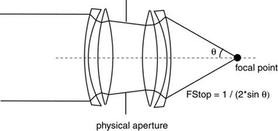
For setting the aperture size, a more useful equation is: fstop = 1 / (2 *
sin(theta)), which relates the f number to the angle defining the
cone of light passing freely through the lens system. You can find a
derivation of this equation (illustrated below) in several optics texts or
online.
With this equation you can compute theta for any fstop value.
To find the size of the physical aperture (which is later used to compute the
exit pupil), simply trace a ray at angle theta from the central axis
through the lens system. The intersection point of this ray with the aperture
plane defines the radius of the aperture. You can use this to compute the
minimum possible fstop, which corresponds to the maximum possible theta
for a given lens. Use the reference implementation to check your aperture size
for different f numbers.
Thick lens transformation
The paper describes a way to implement the thick lens approximation as a 4x4
matrix. It's important to note that the transform they give assumes that
P is the origin. Using the coordinate system you are given in
lensview, you have to be careful about the position of points you want
to transform. For example, if you are calculating the exit pupil, you need to
do: i = Te, where e is a point on the top edge of the physical
aperture, T is the thick lens matrix, and i is the image of
e. However, for this to work correctly you need to translate e.z
by the position of P, so you get: e = e - P, where P is a
signed value. Then after you apply the transformation you need to
translate the result back: i = i + P to get the proper distance along
the axis. (You probably had to do something similar to this when computing
ray/sphere intersections for each lens element). The same is true for imaging a
point on the other side of the thick lens, except you want to replace P
with P'. The paper discusses this, but it might not be clear given the
lensview coordinate system.
Step 3 (Part 2)
For part 2 of this assignment, you will use your camera simulator to create a
realistic camera plugin for pbrt. You will use this model to explore
effects such as depth of field, field distortion, focusing, aperture and
exposure. Once you've completed part 1, this should be relatively painless. You
should be able to port your code directly to pbrt with only slight
modifications. Click here to download a zip file
containing the skeleton code the realistic camera plugin. The file also
contains several pbrt scene files that demonstrate how to use the
realistic camera type. The list of input parameters are as follows (all
values are in millimeters):
-
fstop: the f number to use when calculating the size of the aperture
stop. Your code should report cases where the requested f number is outside the
range of possible values for a given lens.
-
focaldistance: this is the distance from the front lens element (0,0) to
the plane of focus. Set this to f if you want to focus on an object
f millimeters in front of the lens system.
-
filmdiagonal: this is the diagonal size of the film. For example, 35mm
film is standard in most cameras. You can use this to determine the size of the
film plane.
-
specfile: the path to the lens specification file (e.g "fisheye.dat").
-
mode: possible values should be "accurate" and "approximate," where the
former means to use the exact ray tracing routine and the latter refers to the
thick lens approximation.
-
shutterclose: exposure time for the camera, where the default value is 1.0.
Requirements
The scene files in realistic.zip provide you with examples of how to test the
accuracy of your camera simulator. The 'examples' folder contains references
images corresponding to each of the pbrt scenes. Your implementation
should produce similar (ideally identical) results for these examples. The zip
file contains a reference implementation (realistic.dll) you can use to verify
your results.
Suggestions
-
You should trace rays from the image plane through the exit pupil instead of
the rear lens element. In the GenerateRay() function, you can use
ConcentricSampleDisk() to convert sample.lensU and sample.lensV into points on
the exit pupil (i.e. effective aperture).
-
For rays that terminate on the aperture stop or elsewhere in the lens system,
make sure you set mint greater than maxt. pbrt will misbehave if you
don't at least set these ray values.
-
When you compute exposure (i.e irradiance on the film), you can use the
simplified cos^4 falloff and assume that the effective aperture is small
relative to the film. This is not always accurate; you can use the analytic
form factor given in the paper, but it's not required for this assignment.
Note that the GenerateRay() function returns a weight value for each ray.
-
For rendering will full open aperture, you will need to use high sample
densities (probably around 128) to reduce noise. This will increase rendering
substantially, so be sure to keep the sample rates low when you are debugging.
Submission
Write a short web page describing the algorithms you used in your camera
simulator. Email the TA as usual. The web page should consist of:
- Images from the lensview application showing rays traced through
each lens system.
- Data for each lens system, including all of the parameters displayed in
lensview such as the principle planes, focal points, etc.
- Link to a windows executable of your OpenGL lensview program.
- Renderings of the included pbrt scene files (using high sampling
rate).
- Link to your source code for parts 1 and 2.
- (Optional) Any other renderings that demonstrate the features of your
camera plugin.